This document is intended as a guide for Engineers or customers configuring ASMAX equipment when demonstrating different QoS scenarios.
The values in the screen shots are examples only, as these values will be application specific.
ALL the examples have been tested in the Systems Lab and confirmed as a valid working scenario.
It is important to note that scheduling is inherently an uplink only feature and is how bandwidth requests get to the BS TRx.
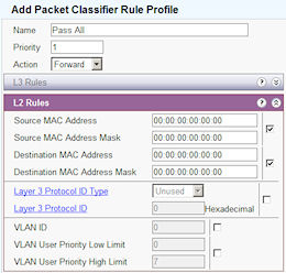
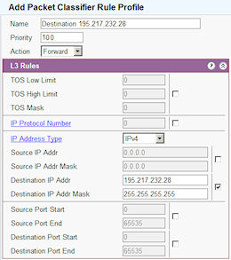
The standard uses the term "priority" for Packet Classifiers but this only determines the order in which the classifiers are matched against the incoming packet. It is the classifier that determines which flow the packet will go into.
Each service flow has a queue assigned to it and therefore a priority, type and latency requirement which the scheduler uses to determine which queue to service first.
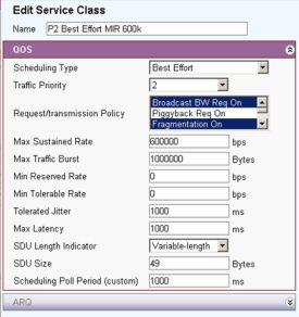
Summary of Scheduling Types:(The references [e.g.11.13.12] are to the IEEE Std 802.16-2004.)
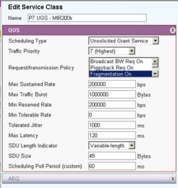
The UGS is designed to support real-time data streams consisting of fixed-size data packets issued at periodic intervals, such as T1/E1 and voice over IP without silence suppression.
The mandatory QoS service flow parameters for this scheduling service are Maximum Sustained Traffic Rate (11.13.6), Maximum Latency (11.13.14), Tolerated Jitter (11.13.13), and Request/Transmission Policy (11.13.12). If present, the Minimum Reserved Traffic Rate parameter (11.13.8) shall have the same value as the Maximum Sustained Traffic Rate parameter.
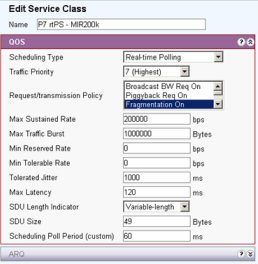
The rtPS is designed to support real-time data streams consisting of variable-sized data packets that are issued at periodic intervals, such as moving pictures experts group (MPEG) video.
The mandatory QoS service flow parameters for this scheduling service are Minimum Reserved Traffic Rate (11.13.8), Maximum Sustained Traffic Rate (11.13.6), Maximum Latency (11.13.14), and Request/Transmission Policy (11.13.12).
The nrtPS is designed to support delay-tolerant data streams consisting of variable sized data packets for which a minimum data rate is required, such as FTP.
The mandatory QoS service flow parameters for this scheduling service are Minimum Reserved Traffic Rate (11.13.8), Maximum Sustained Traffic Rate (11.13.6), Traffic Priority (11.13.5), and Request/Transmission Policy (11.13.12).
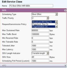
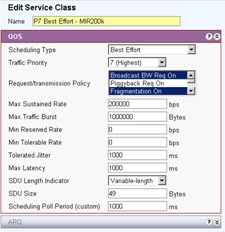
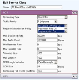
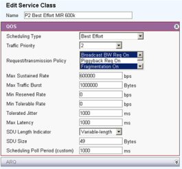
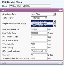
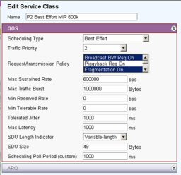
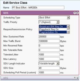
The BE service is designed to support data streams for which no minimum service level is required and therefore may be handled on a space-available basis.
The mandatory QoS service flow parameters for this scheduling service are Maximum Sustained Traffic Rate (11.13.5), Traffic Priority (11.13.5), and Request/Transmission Policy (11.13.12).
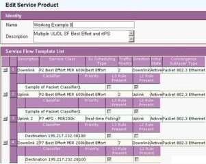
Below are sample screens showing Service Flows for a number of possible setups
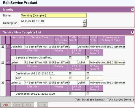
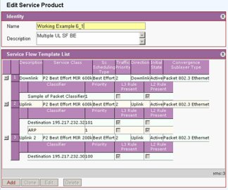
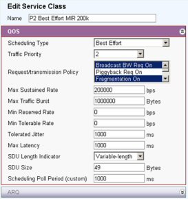
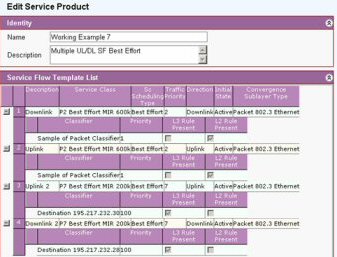
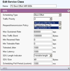
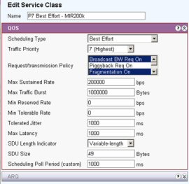
Multiple Uplink Service Flows [Best Effort, P2 & P7]
Multiple Uplink Service Flows &endash; Best Effort [Both P2]
Multiple Uplink/Downlink Service Flows [Best Effort]
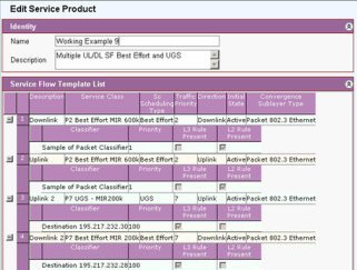
Multiple Uplink/Downlink Service Flows [Best Effort & rtPS]
Multiple Uplink/Downlink Service Flows [Best Effort & UGS]
TOS6
|
Service Product |
Service Class |
Classifiers |
||
|
|
|
Priority |
|
Priority |
|
D/L |
Best Effort 600k |
2 |
Pass All |
|
|
|
| |||
|
U/L |
Best Effort 200K |
7 (High) |
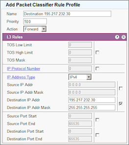
Destination IP 195.217.232.30 |
100 |
|
|
| |||
|
U/L |
Best Effort 600K |
2 |
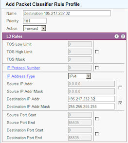
Destination 195.217.232.32 |
101 |
|
|
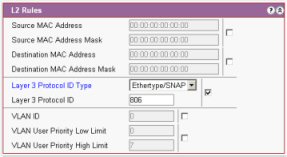
ARP |
1 | ||
Note The ARP Classifier needs to be set so that ARP packets can pass over the uplink. In this traffic uplink packets will only pass to IP 195.217.232.30 and Destination 195.217.232.32. Traffic packets to IP 195.217.232.30 will have the highest priority.

|
Service Product |
Service Class |
Classifiers |
||
|
|
|
Priority |
|
Priority |
|
D/L |
Best Effort 600k |
2 |
Pass All |
|
|
|
||||
|
U/L |
Best Effort 200K |
2 |
Destination IP 195.217.232.30 |
100 |
|
|
||||
|
U/L |
Best Effort 600K |
2 |
Destination 195.217.232.32 |
101 |
|
|
ARP |
1 | ||
Note The ARP Classifier needs to be set so that ARP packets can pass over the uplink. In this traffic uplink packets will only pass to IP 195.217.232.30 and Destination 195.217.232.32
Uncheck all L2 and L3 rules, except "Layer3 protocol ID Type
|
Service Product |
Service Class |
Classifiers |
||
|
|
|
Priority |
|
Priority |
|
D/L |
Best Effort 600k |
2 |
Pass All |
1 |
|
U/L |
Best Effort 600K |
2 |
Pass All |
1 |
|
D/L |
Best Effort 200K |
7 |
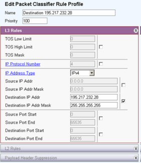
Destination 195.217.232.28 |
100 |
|
U/L |
Best Effort 200K |
7 |
Destination 195.217.232.32 |
101 |
Note The ARP Classifier does not need to be set as ARP packets can pass over the uplink.
|
Service Product |
Service Class |
Classifiers |
||
|
|
|
Priority |
|
Priority |
|
D/L |
Best Effort 600k |
2 |
Pass All |
1 |
|
U/L |
Best Effort 600K |
2 |
Pass All |
1 |
|
D/L |
Best Effort 200K |
7 |
Destination 195.217.232.28 |
100 |
|
U/L |
rtPS 200K |
7 |
Destination 195.217.232.32 |
101 |
Typically this would be used for VOIP calls to Destination 195.217.232.32
|
Service Product |
Service Class |
Classifiers |
||
|
|
|
Priority |
|
Priority |
|
D/L |
Best Effort 600k |
2 |
Pass All |
1 |
|
U/L |
Best Effort 600K |
2 |
Pass All |
1 |
|
D/L |
Best Effort 200K |
7 |
Destination 195.217.232.30 |
100 |
|
U/L |
UGS 200K |
7 |
Destination 195.217.232.28 |
100 |
|
Service Product |
Service Class |
Classifiers |
||
|
|
|
Priority |
|
Priority |
|
D/L |
Best Effort 600k |
2 |
Pass All |
1 |
|
U/L |
Best Effort 600K |
2 |
TOS |
123 |
|
D/L |
Best Effort 200K |
7 |
TOS |
123 |
|
U/L |
Best Effort 200K |
7 |
Pass All |
1 |
This example shows the managing of a work flow using the TOS flag in the Header.
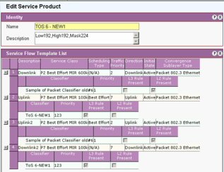
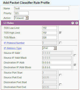
Setting The TOS Byte
In the IP TOS byte model defined in RFC 1349, the TOS byte consists of the 3 bit IP Precedece field (bits 5, 6 and 7) and the 4 bit IP TOS value (bits 1,2,3 and 4). The defined IP precedence values are shown in the table below:
|
|
Precedence Bits |
|||
|
Priority Level |
TOS value |
4 |
2 |
1 |
|
Routine |
0 |
0 |
0 |
0 |
|
Priority |
1 |
0 |
0 |
1 |
|
Immediate |
2 |
0 |
1 |
0 |
|
Flash |
3 |
0 |
1 |
1 |
|
Flash Override |
4 |
1 |
0 |
0 |
|
Critic/ECP |
5 |
1 |
0 |
1 |
|
Internetwork Control |
6 |
1 |
1 |
0 |
|
Network Control |
7 |
1 |
1 |
1 |
|
Decimal Value |
128 |
64 |
32 | |
The IP TOS value fields consists of 4 independent bit fields, the most commonly used of which is the throughput bit (bit 3 in the full TOS byte). If bit 3 is set to 1 this denotes high throughput; If bit 3 is set to 0 this denotes normal throughput.
To select based on the IP precedence use a TOS mask of 254, and select the low and high values based on the decimal values in the table above. e.g. to select exactly just traffic with IP precedence Internetwork Control, set the TOS Low Limit and TOS High Limit to 192. To select traffic with IP precedence of Internetwork Control or Network control, set the TOS Low Limit to 192 and the TOS High Limit to 224.
To select based on the throughput bit, use a TOS mask of 8. To select just normal throughput traffic set the Low limit and High Limit to 0. To select just high throughput set the Low Limit to 1 and the High Limit to 1.
If you wish to select traffic on the basis of both the IP Precedence values and throughput bit, we recommend defining 2 separate classifiers for the same service flow