The shelf alarm panel is usually fitted to the top left or top right of the chassis. It provides two serial connection ports, alarm indication and an interface to telco alarm systems.
The two serial ports provide connections to allow LAT access to the shelf manager tools for each Shelf manager (ShMM 500). Only one SAP exists even with dual redundant shelf managers.
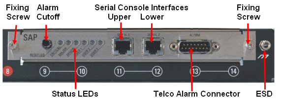
The Shelf Alarm Panel (SAP) is located at the front of the Shelf. It provides:
The alarm cutoff push button (ALARM SILENCE)
3 shelf alarm LEDs (MINOR, MAJOR, CRITICAL)
3 user-definable LEDs (USER1, USER2, USER3)
2 serial console interfaces for both shelf managers (RJ45 connectors)
The telco alarm connector (DB15-male)
The following can be set using the serial ports on the SAP using either terminal access on a PC or mincom if using Linux
Shelf address
Root user password
Date and time
IP network definitions
The SAP provides a telco alarm interface on the DB15-male connector.
The telco alarm interface relay circuits are capable of carrying 60 VDC or 1A with a max. rating of 30 VA.
The SAP accepts timed pulse inputs for clearing minor and major alarm states. There is no reset for the critical state.
Reset is accomplished by asserting a voltage differential from 3.3 V to 48 V for between 200 and 300 ms. The acceptance voltage range is from 0 to 48 VDC continuous (handles up to 60 VDC at a 50% duty cycle). The current drawn by a reset input does not exceed 12 mA.
Telco Alarm LEDs indicate presence of Critical, Major and Minor alarms.
|
State |
Description |
|
Off |
No Alarm triggered |
|
On |
Alarm triggered |
|
Blinking |
Alarm Cutoff (ACO) is activated |
The Telco Alarm Cutoff push button (ALARM SILENCE) on the SAP activates the Alarm Cutoff (ACO) state. When ACO is activated, the active Alarm LEDs blinks and all of the alarm relays are deactivated. The ALARM SILENCE push button only activates the Alarm Cutoff (ACO)state, but does not clear the alarm completely.
The Telco alarm connector is a 15 pin D-type connector. The pinouts are as shown below:
|
Pin |
Name |
Description |
|
1 |
AMIR+ |
MinorReset+ |
|
2 |
AMIR- |
MinorReset- |
|
3 |
AMAR+ |
MajorReset+ |
|
4 |
AMAR- |
MajorReset- |
|
5 |
ACNO |
CriticalAlarm - NO |
|
6 |
ACNC |
CriticalAlarm - NC |
|
7 |
ACCOM |
CriticalAlarm - COM |
|
8 |
AMINO |
MinorAlarm – NO |
|
9 |
AMINC |
MinorAlarm – NC |
|
10 |
AMINCOM |
MinorAlarm – COM |
|
11 |
AMANO |
MajorAlarm – NO |
|
12 |
AMANC |
MajorAlarm – NC |
|
13 |
AMACOM |
MajorAlarm – COM |
|
14 |
APRCO |
PwrAlarm – NO |
|
15 |
APRCOM |
PwrAlarm - COM |
|
Shield |
Shelf-GND |
Shelf Ground |
|
Pin |
Function |
|
1 |
RTS |
|
2 |
DTR |
|
3 |
Tx |
|
4 |
Ground |
|
5 |
Ground |
|
6 |
Rx |
|
7 |
DSR |
|
8 |
CTS |
The serial console default configuration is:
115200 baud (<1metre
cable for 115200 baud)
Hardware Xon
or Xoff
no parity
8 data bits
1 stop bit