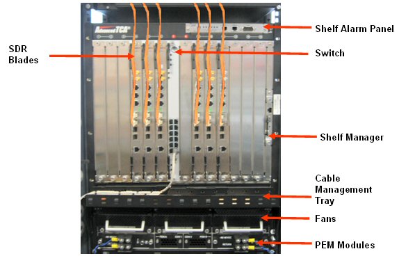
The 14-slot ATCA chassis conforming to the PICMG 3.0 specification is detailed below. The chassis has a dual star backplane with up to two Shelf Managers, fans, fan controllers, filters and power conditioning modules.
The 14-slot chassis has bussed IPMBs and is designed to work with Shelf Managers that are located in the dedicated Shelf Manager slots. The Shelf Manager also contains the Fan Controller for the three pluggable fan trays. If only one Shelf Manager is installed is should be installed in the upper slot.
Three modular fan trays can easily be removed after removing the fan tray cover at the front of the shelf. The display module at the front of the fan tray provides a blue hot-swap LED, amber and red alarm LEDs and a green fan-try-good LED as well as a hot swap push button.
There are 3 Telco Alarm LEDs (minor, major, critical), 1Teleco Alarm push button that activates the alarm cutoff state (ACO). When ACO is activated, the active alarm LEDs blinks and all the alarm relays are deactivated. This button does not clear alarms.
There are two pluggable PEMs (Power Entry Modules). Each PEM provides power terminals for a 25A power feed ( -48V and VRTN). Internally to the PEM these are split into four separate fused feeds, each of these four feeds is protected by two 30A fuses. The minimum input voltage is -40.5VDC and the maximum is -57.0VDC.
Two blades are currently available. SDR blade for the software defined radio and Switch blade for the Ethernet Switch.
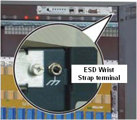
The ESD Wrist Strap terminal is located on the upper front side of the shelf, and must be used prior to working on any part or electronic component.
Before inserting any blades, turn on the -48V and measure the voltage on the PEMs. Note when the chassis are powered the fans go to full speed and then slow down once the Shelf Manager control loop kicks in. If the -48V is connected the wrong way the chassis will not power up.