Prior to commissioning the engineer should be provided with job specification detailing the setup requirements for the ATCA rack
If the job specification specifies that the SDR requires GPS timing, check that a GPS module is present. If not, the installer should be contacted.
If the job specification specifies that the traffic port is on the front panel of the blade and using an external switch, ensure that a port is available on an external switch. Check with the NOC that the switch has been configured.
If the job specification specifies that the traffic port is on the backplane, ensure that an Ethernet switch is inserted into slot 7 of the ATCA rack. This should have been configured in the previous section.
Ensure that the associated SCRTs have 48v supplied and that the OBSAI cables for the SCRTs are available at the ATCA rack and clearly labelled with SCRT ID.
If the specification specifies that a blade is to be a Primary Master, insert the blade into slot 6 on a 14 slot ATCA rack or slot 3 on a 5 slot ATCA rack.
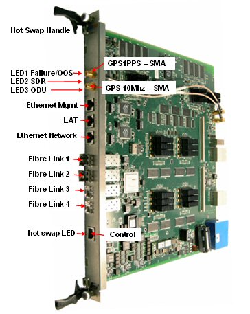
Connect the 1PPS and 10MHz connectors on the front of the blade to the 1PPS and 10MHz connectors on the GPS module using Sync Cables (SMA to SMA).
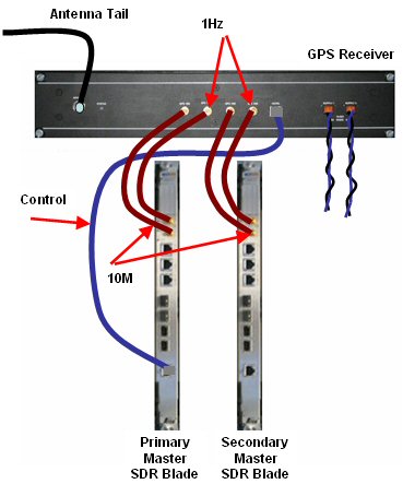
If the specification specifies that the primary master blade manages the GPS module then connect the GPS management connector on the front panel of the SDR blade (identified by the "CNTRL" label) to the management port of the GPS module. using RJ45-RJ45 CAT5 control cable.
If the specification specifies that the blade is to be a secondary master, insert the blade into slot 9 for a 14 slot on a ATCA rack or slot 4 for a 5 slot on a ATCA rack.
Connect the 1PPS and 10MHz connectors on the front of the blade to the 1PPS and 10MHz connectors on the GPS module using sync cables (SMA to SMA).. See diagram above.
If the job sheet specifies that the Secondary Master blade manages the GPS module then connect the GPS management connector on the front panel of the SDR blade (identified by the "CNTRL" label) to the management port of the GPS module using RJ45-RJ45 CAT5 control cable.
If the specification specifies that the blade is to be a slave, check that there is already a blade plugged into the primary master slot and / or the secondary master slot of the ATCA rack and that at least one is correctly wired to the 10M and 1Hz. Also check that the GPS module management port is wired to the blade which is specified as managing the GPS module. If this is not the case, the installer should be contacted.
If the primary master and the secondary master are correctly wired, insert the blade into any free slot.
With the blade plugged into a slot, the installer shall check the status of the LEDs on the blade
If the LED status is correct, the blade should be configured using a local Engineering PC. The PC should be configured with an IP address of 192.168.0.1. and a network mask of 255.255.255.0
Connect the Ethernet port of the PC to the Ethernet port labelled "Data" on the front panel of the blade. A straight Ethernet patch cable should be used.
Open a browser on the PC.
In the browser address bar, type 192.168.0.100
When prompted, enter the username and password as follows
User name : asmax
Password : The password as set as the SNMP read-write community, default is “private”
The BS configuration WEB page should appear. This will be required later.
Connect the SCRT OBSAI cables to the SDR blade OBSAI ports. The job specification should specify the mapping of SCRT ID to Obsai port ID for the SDR blade being installed.
The front panel of the SDR blade has 4 OBSAI ports labelled SPF1 up to SPF4. Each port can connect to a single SCRT. Release 4 supports 2 SCRTs per SDR blade and these will operate in the same sector and must plug into SFP1 and SFP2. Also in release 4, only the SCRT connected to SFP1 will transmit but both can be configured to receive for uplink diversity operation.
The ends of the OBSAI cables at the ATCA rack should be labelled with the SCRT ID. This would have been done when the SCRTs and associated cables were physically installed.
The breakers should be switched on to provide power to the SCRTs.
From the Engineering PC, use SSH (or PuTTY on a Windows machine) to log into the SDR blade:
password: asmaxroot
From the command line, ping 1.0.0.1 to ensure that the first SCRT is contactable (note: it may take up to two minutes for the SCRT to fully boot).
When successful ping the second SCRT at 2.0.0.1.
If contact to any SCRT fails, check the OBSAI and 48V wiring to the SCRTs (Note: do not look directly into the end of the connector).
From the BS WEB page, click on "Set Base Station ID".
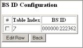
Check the box under the column labelled # and then click "Edit Row"
Enter a BSID in the format, it must me XXXXXX:XXXXXX where each “X” is a hexadecimal digit (so 6 digits, a colon, 6 more digits).
Click "Save"
Click on "SNMP Config"
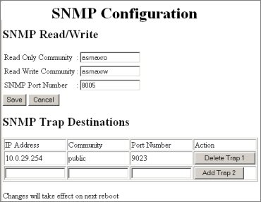
Under "SNMP Trap Details", Click "Add Trap 1" enter IP address, Community and Port Details as specified in the job specification.
Enter the Read Only Community, Read Write Community and SNMP Port Number as specified in the job specification.
Click "Save"
Details will not take effect until the SDR is reset. DO NOT RESET THE SDR AT THIS STAGE.
Click on "GPS Config".
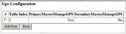
Click on "Edit Row".
With the row index set to 1, select whether the GPS module should be managed from the Primary Master or the Secondary Master. This is specified in the job specification.
Click "Save".
Click on "NTP Config".
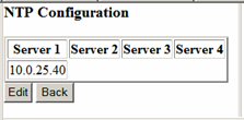
Click "Edit"
Enter the NTP servers as specified in the job specification.
Click "Save".
Click on "Network Configuration" and then enter the details as specified in the job specification.
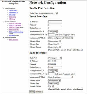
Traffic Port : Select Backplane or Front.
IP Address/Network/Default Gateway: Set the IP address of the shelf for the interface being used to the selected IP address and subnet mask (The IP address must be provided to the installation team together with the other installation job information – location, equipment physical build and antenna details) Leave unused interface blank.
Management VLAN/VLAN Tag: Set the Management VLAN to the required setting
Management IP Mode: Set to Static IP address for interface being used , set to Do not configure any IP address for interface not being used.
Ethernet Mode/Rate/Duplex: Set to Autonegotiate
Save Configuration
 Warning:
Check before you select "Save". If you configure an address
that is not routable from your network location, you will lose contact
with the base station and may need physical access to the equipment for
recovery. Changes will take effect on next reboot
Warning:
Check before you select "Save". If you configure an address
that is not routable from your network location, you will lose contact
with the base station and may need physical access to the equipment for
recovery. Changes will take effect on next reboot
When all the above steps have been completed, click "Reboot Basestation".
Disconnect the blade Ethernet port from the PC.
If not using an ATCA switch connect the Ethernet port on the front panel labelled DATA to the appropriate port of an external Ethernet switch.