Before starting the installation ensure availability of port planning information:
Separate Ethernet management and traffic ports or an Ethernet port with combined management and user traffic.
Switch Management in Network Ethernet (in band) or in separate Management Ethernet (out of band).
IP addresses for management.
Set local PC I/P address to 192.168.1.100
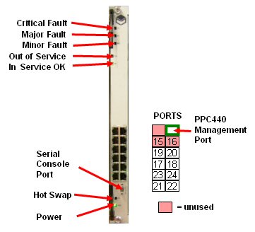
In the examples below the network is configured to be connected to port 22 but any port 17 -22 may be used as specified in the job specification. (Note ports 15 and 16 should not be used).
Connect from PC network port to the management
port of the switch blade.
Note: The PC IP address must be in the same subnet as Switch
IP address
From a browser connect to 192.168.1.1
On opening screen click Login: The login is admin and no password is set (leave blank)
The default screen is shown below.
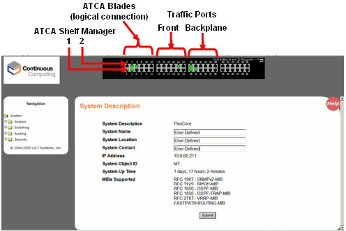
Enter a System name/ location/system/system contact.
Click submit.
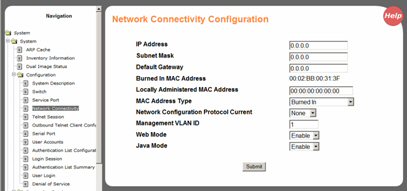
From the side menu select Configuration/Network Connectivity.
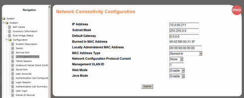
Enter the IP Address/Subnet Mask/Default Gateway for the switch. Leave all other fields at default as above unless specific values are required.
Click Submit
Select System/Configuration/User Accounts and create user accounts for user access.
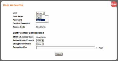
Click Submit
The management of the switch can be done over the same Ethernet as the traffic, or It can use another Ethernet connection exclusively for management. The advantage of using the latter is that the switch can still be managed if the Network Ethernet is down.
1. Set Network Connectivity Configuration IP address and mask to 0.0.0.0
2. Set Service Port Configuration with IP address.
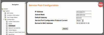
3. Click Submit
1. Set Network Connectivity Configuration IP address and mask
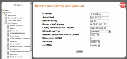
2. Click Submit
The table below shows the mapping between the ports of SDR in the ATCA physical slots and the port numbers in the switch.
|
Physical Slot |
Port |
|
Shelf Manager |
1 |
|
1 |
38 |
|
2 |
36 |
|
3 |
34 |
|
4 |
32 |
|
5 |
30 |
|
6 |
28 |
|
9 |
29 |
|
10 |
31 |
|
11 |
33 |
|
12 |
35 |
|
13 |
37 |
|
14 |
39 |
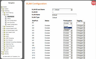
From the side menu select System/Switching/VLAN Configuration.
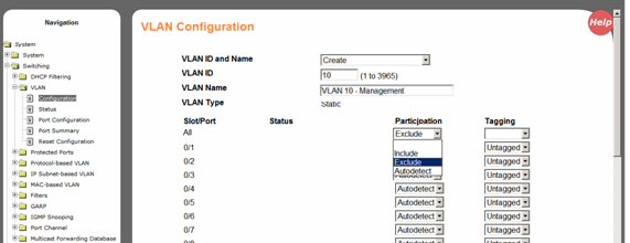
Select create for VLAN ID and Name, add VLAN ID and Name.
For the “Slot/Port” entry labelled ALL, set the “Participation” drop down list box to “exclude. Then submit.
Individually set the participation
to 'include' and tags as required, for the slots in the ATCA rack that
are populated by SDR blades and/or ports on the switch with Ethernets
connected. The example below shows the management being set for blades
in connected to ports 28, 29 and 31. See
port mapping above.
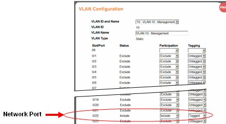
Note: The Network port also has to be included for the management
to work over the network.
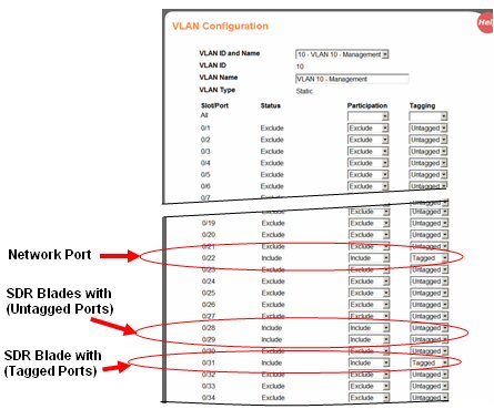
Click Submit to set.
If untagged management is used then the Port VLAN should have ingress filtering enabled. (Note: This is only required when using untagged management on a port.)
From the side menu select System/Switching/VLAN Port Configuration.
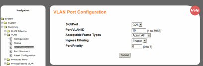
Select port from the drop list.
Set port VLAN ID number. (In the example the management is on VLAN 10.)
Set Acceptable frame types to 'Admit All'.
Set Ingress filtering to 'Enable'.
Click Submit.
From the side menu select System/Switching/VLAN Configuration.
Select create for VLAN ID and Name, add VLAN ID and Name specified in job specification.
From the All Participation drop box set to exclude and then submit.
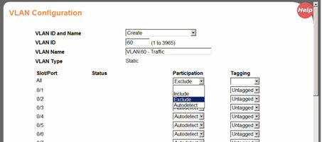
Individually set the participation to 'include' for the port to be included. The screen shot below shows port 22 traffic added to the VLAN. Note: The Network port also has to be included for the Traffic to pass over the network.
Click Submit.
Repeat for all the ports connected to the slots (blades).
From the side menu select System/Switching/VLAN Configuration.
Select Default VLAN .
From the All Participation drop box set to exclude.
Click Submit to set.
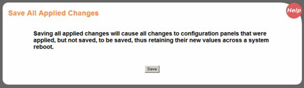
After Management and Traffic VLANs have been select System/System/System utilities/Save and Apply changes from the side menu. Click Save.
This completes the switch configuration.