|
Tool |
|
Large Crosshead Screw driver Phillips # 3 or Pozidrive # 3 |
|
Small flat blade Screwdriver |
|
Small flat blade Screwdriver |
|
13mm or 1/2" open ended Spanner" |
|
10mm or 13/32" open ended Spanner |
|
M8 open ended Spanner |
|
M10 open ended Spanner |
|
Wire strippers |
|
Wire cutters |
|
Ring terminals crimp tool |
|
RJ45 crimp tool |
|
Additional Items required (not provided by Airspan) |
|
Spare RJ45 connectors |
|
Cable ties |
|
Outdoor Cat5 Ethernet cable. From the SDR to the local Ethernet connection. |
|
Ring terminal for earth strap. M5/ M6 |
|
Earth strap cable (4-6mm). (yellow and green cable) |
|
Weatherproof / Outdoor mains cable splice kit or termination box. |
Wall/Roof feed-through is required For Ethernet and AC Supplies.
Access is required to and within risers and roof space.
Cable trays should be provided for routing to the equipment and they should have adequate strength to support the cables.
Horizontal cable runs must be adequately protected.
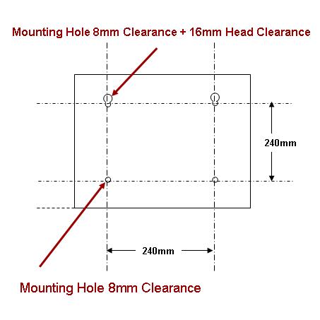
SDR Mounting Plate
The SDR enclosure is fitted on to a Mounting Plate (Not provided by Airspan). The mounting should be drilled as shown below. It is the responsibility of the provider to ensure that the structure is sufficiently robust to support the SDR
Normally the SCRT should be pole mounted to a 30mm (1.25") pole. Where more than one SCRT is to be provided the poles should be at least 1 metre apart.
The bottom of the antenna is at least 1 metre above the rooftop or any parapets. (the antenna may need to be raised higher to allow for any downtilt.)
The radiating face of the antenna is no further back than I metre from the edge of the building.
The antenna is mounted on a 100mm mounting pole The pole should be at least 1.3 metres long.
There should be no other antennas or obstructions above, below or to the side of the antenna for at least 1 metre.
The antenna mounting structure should be stable and sufficiently strong to support such a pole.
The antenna should have a unobstructed beam width for a 100 metres.
Cable trays are in place, provide routing to the proper destinations and that they have adequate strength to support the feeders.
Horizontal feeder runs are adequately protected.
Adequate Earthing is provided.
SDRs that have the GPS option have a GPS antenna and four metres of cable included. The first consideration for a GPS antenna is a clear view of the sky, preferably 360 degrees. In the usual installation, the GPS antenna is located low and close to the equipment building roof. The GPS antenna is provided with a bracket that should be attached to a suitable pole/mast at the base of the SDR-micro. The bracket fits a pole 25-80mm diameter.
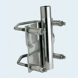
GPS Antenna Bracket
a) The antenna must be mounted in an upward position.
b) The antenna should be installed at the highest possible point available at the site. This is to ensure that any surrounding obstacles (trees, buildings or other installations, etc.) are not exceeding a 20° elevation angle.
c) To avoid influence of reflected waves, the antenna must not be installed less than 2m away from metallic objects with a dimension greater then 20 cm.
d) Antenna installation should be avoided in close proximity with other receivers or transmitters susceptible to cause interference.
e) Lightning protection should be in accordance with section 5. Lightning Protection