Standard system configurations utilise a compact vertically polarised sector antenna which mounts and connects directly to the SCRT. Independently mounted antennas can also be accommodated. Antennas are available for a range of frequency bands and sector angles. For more details see the Airspan Product Catalog 005-8404-000
HiperMAX-micros that have the GPS option have a GPS antenna and four metres of cable included. HiperMAX requires the antenna to be mounted on the mast or a rooftop and cabled to the GPS shelf in the ATCA rack. The first consideration for a GPS antenna is a clear view of the sky, preferably 360 degrees. In the usual installation, the GPS antenna is located low and close to the equipment building roof or mast.
The DC feed should be protected against lightning surges as the antenna ends. For the HiperMAX-micros protection also has to be provided at the SDR. For HiperMAX protection also has to be provided at the building entry. For more details see the Airspan Product Catalog 005-8404-000
The sections below provide list the main characteristics of the unit.
|
|
Height (mm) |
Width (mm) |
Depth (mm) |
Weight (kg) |
|
SCRT (excl bracket and Antenna): |
340 |
270 |
140mm |
6.5kg typical 6.5kg max |
|
WiMAX Antenna |
650 |
200(226 inc Bracket) |
100mm |
1.3kg max |
|
GPS Antenna |
55mm |
89mm |
254mm |
0.15kg |
|
DC power feed lightning surge protection |
115mm |
90mm |
55mm |
0.2kg |
The following interfaces are provided on the SCRT:
|
Port Name |
Description |
|
Power Input |
Nominal -48V DC power input. Note that the SCRT operational voltage range is nominally -40.5V to -57.5V and power consumption is typically 50-60Watts per SCRT. Connector type : Weatherproof Proprietary Connection, compatible with connector supplied as part of pre-terminated power cable assembly from Airspan. Power cables for HiperMAX-micro are connectorised at both ends and are available in 3, 10, 30 and 100 metre lengths. Power cables for HiperMAX are connectorised at the SCRT end only and are available in 30 and 100 metre lengths. |
|
Optical Port |
The SDR & Masthead Transceiver are connected via a 2 channel multimode fibre interconnect in accordance with the OBSAI standard. Connector type: Outdoor Connector (ODC) supplied as part of pre-terminated fibre assemblies. The outdoor fibre interconnect is common to both HiperMAXand HiperMAX-Micro is available in 3, 10, 30 and 100 metre lengths. |
|
RF Port |
50 Ohm RF connector for external antenna. Connector type N-type |
|
Earth Stud |
Each unit is fitted with an earth stud (M6 Posi-drive screw) |
The SCRT can be used either with an antenna mounted on the front of the SCRT or with a remotely attached RF antenna. The SCRT can also be pole mounted or plate mounted. The SCRT requires a solar shield to protect the electronics from elevated temperatures, and various configurations are available depending on which mounting method and which antenna arrangement is used. Specifically the following kits are currently available:
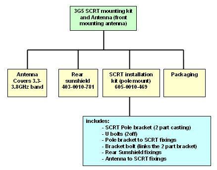
1. Mounting kit and direct mounting antenna for pole mounting
2. Installation kit for independently mounted antenna and pole mounted SCRT
3. Installation kit for independently mounted antenna and plate mounted SCRT
Other kits may be made available to cater for other mounting arrangements. Note that the SCRT and the mounting kits are generally supplied as two separate boxes (except for the 4.9gHz SCRT).
Each SCRT connects to an SDR base-band unit using an optical fibre cable. Depending on the type of SDR unit in use, the cable termination at the SDR end may differ (different terminations for SDR-Micro and SDR-ATCA). Each SCRT also requires 48volt power which is supplied from the SDR-Micro or an alternative power supply when the HipexMAX-SDR (ATCA version) is used.
Surge protection kits are also available for added protection for HiperMAX installations.
Note: For pole mounted installation, the SCRT requires a 40-45cm pole diameter. The pole should be made of galvanised steel and must be earthed to ensure that a discharge path is available for lightning surges. In cases where the pole is painted or made of other materials or where the pole is not earthed, a substantial lightning conduction strap must be fitted to the earth terminal of the SCRT. Similarly for plate mounting installations, the installer must ensure that good earth is available to the SCRT. If the plate if not earthed or is painted, then a lightning conduction strap must be fitted to the SCRT.
Three installation kits are currently available and these are briefly described below:
The figure below shows an SCRT with a front mounted antenna. Note that in this arrangement only a rear mounting sunshield is required.
This corresponding kit is structured as follows:
The picture below shows a view of the SCRT when used with an independently mounted antenna. Note that in this case, both a front mounting and a rear mounting sunshield are required.
This corresponding kit is structured as follows:
The picture below shows a view of a plate mounted SCRT when used with an independent antenna. Note that in this case, only a front mounting sunshield is required.
This corresponding kit is structured as follows: