Performing a Final System-Level Check
When and where to use:
Perform a final system level check for every channel in the system to confirm that the output levels for each site are no more than 0.3 dB of each other for each of the remaining test frequencies.Procedure:
- Make several photocopies of the “Recovered Level Entry Log” table in theMLC 8000 Setup Guide. This table serves as a log for recovered signal levels at various test frequencies. The data entered is used to check and verify system alignment.
- From the MLC 8000 Configuration Tool main menu, select . In the Voter Link Delay Management and Calibration window, select the IP Simulcast: BR Calibration tab.
- Use the MLC 8000 Analog Comparator to generate the 7 Hz test frequency, then repeat for the other test frequencies: 20 Hz, 15 Hz, 12 Hz, 10 Hz, and 5 Hz.
Voter Link Delay Management and Calibration Window – BR Calibration Tab for an IP Simulcast System 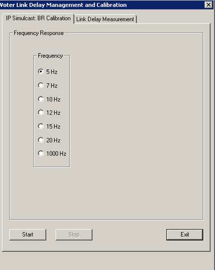
- Set the MLC 8000 Analog Comparator to generate a 7 Hz tone. Click Start.
- Observe the reading on the DSA.
NoteIn 5 through 7, verify that the output of the optimization receiver is approximately 60%. See “Troubleshooting Misaligned Reference Modulation Compensation (Final System Level Check — IP Based)” in the MLC 8000 Setup Guide if the levels between sites for a given frequency vary by more than 0.3 dB of the reference site.
- In the copy of the “Recovered Level Entry Log” in the MLC 8000 Setup Guide that is used for your system log, enter the 7 Hz reference level obtained in “Performing Fine Amplitude Adjustment” in the MLC 8000 Setup Guide.
- Set the frequencies and note the levels as follows:
Frequency of the MLC 8000 Analog Comparator generator Recovered Level Entry Log for the site Set to 20 Hz. Enter the level recovered from the optimization receiver in the 20 Hz column. Set to 15 Hz. Enter the level recovered from the optimization receiver in the 15 Hz column. Set to 12 Hz. Enter the level recovered from the optimization receiver in the 12 Hz column. Set to 10 Hz. Enter the level recovered from the optimization receiver in the 10 Hz column. Set to 5 Hz. Enter the level recovered from the optimization receiver in the 5 Hz column. - Repeat 1 through 7 for all sites on the channel.
- Re-enable the measured channel and disable the next channel you want to measure.
- Repeat 3 through 9 for all channels in the system.
NoteThe output of the DSA begins to drop when the frequency generated falls below 10 Hz. This drop causes the roll-off seen in the chart and is acceptable.
- Verify that for each given frequency, the levels recorded in the “Recovered Level Entry Log” table in the MLC 8000 Setup Guide are no more than 0.3 dB different for each site at a given frequency. If the levels between sites for a given frequency vary by more than 0.3 dB, this variance indicates:
- One or more of the digital gains of the MLC 8000 Subsite Link Converters' require adjustment. For a site that exceeds 0.3 dB difference from the reference site at one of the test frequencies, adjust the MLC 8000 Subsite Link Converter Digital Gain up or down 0.1 dB towards the reference site value and repeat measurements for that site at each test frequency.
- A hump in the MOD COMP waveform indicates that the low frequency (5 Hz, 7 Hz, 10 Hz) levels are hotter than the levels at the higher frequencies (12 Hz, 15 Hz, 20 Hz). In this case, decrease the MOD COMP level.
- A dip in the MOD COMP waveform indicates that the low frequency (5 Hz, 7 Hz, 10 Hz) levels are decreasing too rapidly relative to the levels at the higher frequencies (12 Hz, 15 Hz, 20 Hz). In this case, increase the MOD COMP level.