CCGW Wiring Requirements for Receiving the Channel Active Indication from the MLC 8000 Analog Comparator
This section provides information for connecting the MLC 8000 RJ45 cable to a Site Gateway (CCGW) for the case where the CCGW will receive channel active indication from the MLC 8000 analog comparator. The following figure describes the connection between MLC 8000 Analog Comparator (VGU) and the CCGW with CTI. This connection requires additional CTI logic converter hardware to transfer the voltage properly between the MLC and the CCGW.
NoteThe CTI part number is S2-61418. The Motorola drop-ship part number is DSS261418.
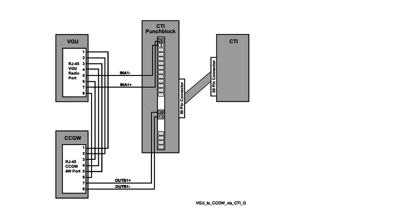
NoteAll connections shown are made through the punchblock.
| VGU | CCGW | CTI Punchblock | ||||
|---|---|---|---|---|---|---|
| Pin No. | Signal | Wire Color | Pin No. | Signal | Pin No. | Signal |
| 1 | Audio Out+ | White/Orange | 1 | TIP2 | ||
| 2 | Audio Out- | Orange | 2 | RING2 | ||
| 3 | Audio In+ | White/Blue | 5 | TIP1 | ||
| 4 | Audio In- | Blue | 4 | RING1 | ||
| 5 | Channel Active | White/Green | 1 | In A1- | ||
| 6 | PTT from Console | Brown | 3 | |||
| 7 | 5V | Green | 26 | In A1+ | ||
| 8 | VGND | White/Brown | 6 | |||
| CTI GPIO | CCGW | |||
|---|---|---|---|---|
| Pin No. | Signal | Wire Color | Pin No. | Signal |
| 38 | Out B1+ | White/Orange | 7 | |
| 13 | Out B1- | Orange | 8 | |