CENTRACOM to MLC 8000 through CTI
The following scheme describes the connection of CENTRACOM to MLC 8000 when CENTRACOM receives Channel Activation indication. This connection requires additional CTI logic converter hardware to transfer the voltage properly between the MLC and the console.
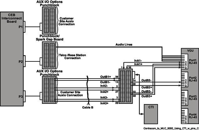
The following is an example of a CENTRACOM to MLC 8000 with CTI connection. Note the punch blocks and the cabling.
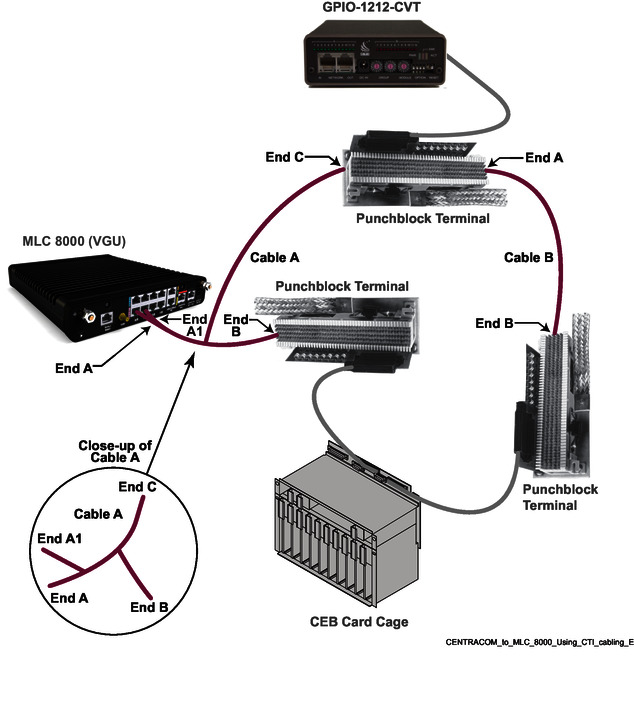
End A and End C:
Cable A:The following table provides additional information for the connection of Cable A.
| End A, | VGU Port 1 | End B, | End C, | |||
|---|---|---|---|---|---|---|
| Pin No. | Signal | Wire Color | Pin No. | Signal | Pin No. | Signal |
| 1 | Audio Out+ | White/Orange | (*) | 4-Wire As input | ||
| 2 | Audio Out- | Orange | (*) | 4-Wire As input | ||
| 3 | Audio In+ | White/Blue | (*) | 2-Wire As output | ||
| 4 | Audio In- | Blue | (*) | 2-Wire As output | ||
| 5 | Channel Active | White/Brown | 1 | In A1- | ||
| 6 | PTT from Console | White/Green | 15 | Out B3- | ||
| 7 | 5V | Brown | 26 | In A1+ | ||
| 8 | VGND | Green | 40 | Out B3+ |
The following table provides additional information on the connection for Repeat On/Off.
| End A1, | End C, | ||||
|---|---|---|---|---|---|
| VGU Port 2 | CTI Punchblock | ||||
| Pin No. | Signal | Wire Color | Pin No. | Signal | Notes |
| 1 | Audio Out + | White/Orange | Not Connected | ||
| 2 | Audio Out - | Orange | Not Connected | ||
| 3 | Audio In + | White/Blue | Not Connected | ||
| 4 | Audio In - | Blue | Not Connected | ||
| 5 | Channel Active | White/Green | Not Connected | ||
| 6 | REPEAT_ON/OFF | Brown | 14 | Out B2+ | REPEAT_ON/OFF |
| 7 | 5V | Green | Not Connected | ||
| 8 | VGND | White/Brown | 39 | Out B2- | |
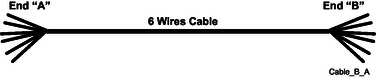
Cable B: (As shown in 4-Wire MLC 8000 to CEB Cabling Including CTI E&M)
Use the open-ended cable with the punch block.
The following table applies to 4-Wire MLC 8000 to CEB Cabling Including CTI E&M.
| VGU | VGU | END A, | END B, | ||||
|---|---|---|---|---|---|---|---|
| PORT 1 | PORT 2 | CTI GPIO Punch Block | CEB Interconnect Board Plug P3 Line Connector | ||||
| Pin No. | Signal | Pin No. | Signal | Pin No. | Signal | Pin No. | Signal |
| 7 | 5V | 26 | In A1+ | ||||
| 5 | Channel Active | 1 | In A1- | ||||
| 27 | In A2+ | (*) | |||||
| 2 | In A2- | (*) | |||||
| 28 | In A3+ | (*) | |||||
| 3 | In A3- | (*) | |||||
| 38 | Out B1+ | (*) | |||||
| 13 | Out B1- | (*) | |||||
| 8 | VGND | 39 | Out B2+ | (*) | |||
| 6 | REPEAT_ON/OFF | 14 | Out B2- | (*) | |||
| 8 | VGND | 40 | Out B3+ | (*) | |||
| 6 | PTT from Console | 15 | Out B3- | (*) | |||
| Slot 1 Function | P2 | Slot 7 Function | P2 |
|---|---|---|---|
| 4-Wire | 24 | 4-Wire | 11 |
| 4-Wire | 49 | 4-Wire | 36 |
| 2-Wire | 23 | 2-Wire | 12 |
| 2-Wire | 48 | 2-Wire | 37 |
| Slot 2 Function | P2 | Slot 8 Function | P2 |
| 4-Wire | 21 | 4-Wire | 8 |
| 4-Wire | 46 | 4-Wire | 33 |
| 2-Wire | 20 | 2-Wire | 9 |
| 2-Wire | 45 | 2-Wire | 34 |
| Slot 3 Function | P2 | Slot 9 Function | P2 |
| 4-Wire | 18 | 4-Wire | 5 |
| 4-Wire | 43 | 4-Wire | 30 |
| 2-Wire | 17 | 2-Wire | 6 |
| 2-Wire | 42 | 2-Wire | 31 |
| Slot 4 Function | P2 | Slot 10 Function | P2 |
| 4-Wire | 15 | 4-Wire | 2 |
| 4-Wire | 40 | 4-Wire | 27 |
| 2-Wire | 14 | 2-Wire | 3 |
| 2-Wire | 39 | 2-Wire | 28 |
| BIM in Cardcage Slot | Punch Block | Punch Block PIN Number |
|---|---|---|
| 1 | P1 | 44 |
| 1 | P1 | 19 |
| 2 | P1 | 43 |
| 2 | P1 | 18 |
| 3 | P1 | 37 |
| 3 | P1 | 12 |
| 4 | P1 | 31 |
| 4 | P1 | 6 |
| 7 | P3 | 44 |
| 7 | P3 | 19 |
| 8 | P3 | 43 |
| 8 | P3 | 18 |
| 9 | P3 | 37 |
| 9 | P3 | 12 |
| 10 | P3 | 31 |
| 10 | P3 | 6 |
BIMS cannot be installed into slots 5 and 6 in the cardcage.
This table assumes that the Aux 1 board (BLN6664) is jumpered for aux 4 to be Channel Active Indication input.
See the CENTRACOM Gold Series Installation manual for jumpering tables for the Aux 1 board.
| BIM in Cardcage Slot | Punch Block | Punch Block PIN Number |
|---|---|---|
| 1 | P1 | 20 |
| 1 | P1 | 23 |
| 2 | P1 | 17 |
| 2 | P1 | 14 |
| 3 | P1 | 11 |
| 3 | P1 | 8 |
| 4 | P1 | 5 |
| 4 | P1 | 2 |
| 7 | P3 | 20 |
| 7 | P3 | 23 |
| 8 | P3 | 17 |
| 8 | P3 | 14 |
| 9 | P3 | 11 |
| 9 | P3 | 8 |
| 10 | P3 | 5 |
| 10 | P3 | 2 |
BIMS cannot be installed into slots 5 and 6 in the cardcage.
This table assumes that the Aux 1 board (BLN6664) is jumpered for aux 4 to be Channel Active Indication input.
See the CENTRACOM Gold Series Installation manual for jumpering tables for the Aux 1 board.
| BIM in Cardcage Slot | Punch Block | Punch Block PIN Number |
|---|---|---|
| 1 | P1 | 49 |
| 1 | P1 | 24 |
| 2 | P1 | 38 |
| 2 | P1 | 13 |
| 3 | P1 | 32 |
| 3 | P1 | 7 |
| 4 | P1 | 26 |
| 4 | P1 | 1 |
| 7 | P3 | 49 |
| 7 | P3 | 24 |
| 8 | P3 | 38 |
| 8 | P3 | 13 |
| 9 | P3 | 32 |
| 9 | P3 | 7 |
| 10 | P3 | 26 |
| 10 | P3 | 1 |
BIMS cannot be installed into slots 5 and 6 in the cardcage.
This table assumes that the Aux 1 board (BLN6664) is jumpered for aux 4 to be Channel Active Indication input.
See the CENTRACOM Gold Series Installation manual for jumpering tables for the Aux 1 board.