Examples of Trunking Configurations That Can Share Equipment
MLC 8000 Analog Comparators, MLC 8000 Subsite Link Converters, and conventional base radios supporting Ethernet-based digital, analog, or mixed mode channels can be deployed at an ASTRO® 25 trunked site, where the conventional system shares the transport equipment, and timing and frequency reference devices when capacity is available. Trunked RF site (repeater or simulcast) cabinet equipment, as well as transport equipment and timing equipment, can be shared between conventional and trunked channels.
The following site types scenarios are supported:
Sharing of transport equipment that is already installed at a trunked IP Simulcast subsystem by analog conventional channel equipment.
Sharing of transport equipment that is already installed at a trunked IP Simulcast subsystem by analog conventional channel equipment, plus sharing of site reference/timing equipment that is already installed at a trunked subsite.
Integration of analog conventional channel equipment into a GTR 8000 Expandable Site Subsystem, plus sharing of transport and site reference/timing equipment that is already installed at a trunked subsite. The Conventional Expandable Site Subsystem can be installed in place of a Conventional Base Radio.
For more information about the GTR 8000 cabling, refer to the Wireline & V.24 Subpanel of the GTR 8000 Expandable Site Subsystem junction panel, in the GTR 8000 Expandable Site Subsystem Feature Guide.
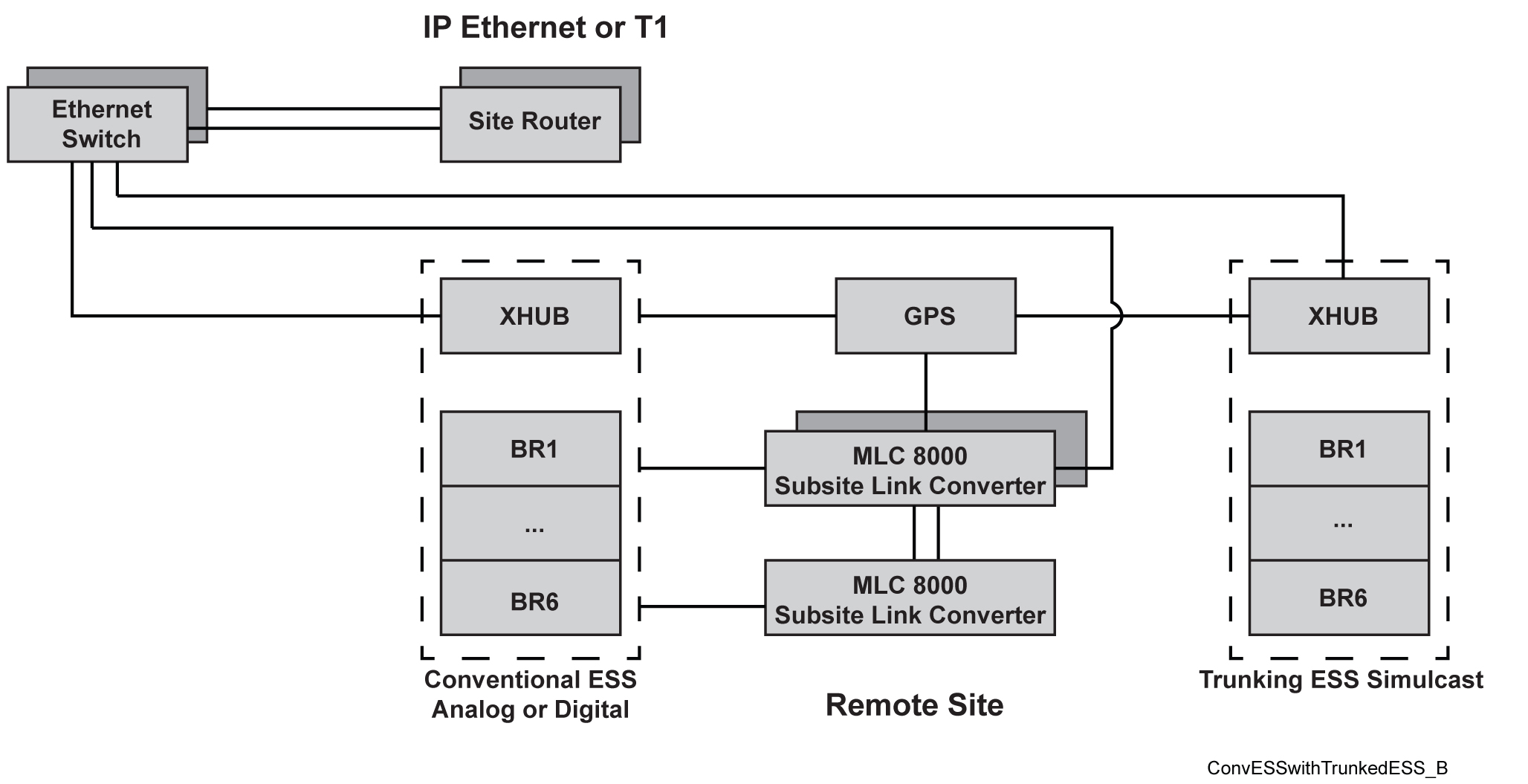
The following figure illustrates a common system configuration where Conventional IP Simulcast equipment shares existing Trunking subsite equipment. The figure shows that an external Ethernet switch can be used when the existing Ethernet switch port capacity of the Expandable Site Subsystems is insufficient. This configuration requires at least one available Ethernet port on the Expandable Site Subsystem to connect to the external Ethernet switch.
Example Diagram Conventional Expandable Site Subsystem Analog or Digital Co-located with Trunking Expandable Site Subsystem
ImportantIn trunked simulcast subsites, external HP Ethernet switches are already present if the High Availability feature was not implemented. Avoid manually re-configuring the external switch because any manual configuration is lost when the switch is rebooted and the ports return to their defaults. Instead, avoid manual configuration by selecting ports from the Motorola Solutions-provided configuration based on the speeds and duplex required. (The device names associated with the ports in the Motorola Solutions-provided configuration file may not match the device type you are connecting to this external switch.)
For an existing switch, which previously had MAC Port Lockdown enabled, the following must occur if devices are added to the switch:
Disable MAC Port Lockdown.
Push the new Motorola Solutions-provided configuration files with the added devices to switches.
Attach devices to chosen ports.
Enable MAC Port Lockdown from the core.
NoteAnalog IP Simulcast is only supported in an Analog configuration. The connection between the MLC 8000 Subsite Link Converter and base radio is 4-wire only. 2-wires are also OK in a receive only base radio (such as GPW 8000 Receivers). The MLC 8000 Analog Comparator and MLC 8000 Subsite Link Converter require a GPS time reference only if the MLC 8000 Subsite Link Converter is connected to a Tx/Rx or Tx only BR. An Rx only BR does not require the GPS.
NoteDigital IP Simulcast is not supported in an MLC 8000 Mixed Mode configuration. Digital IP Simulcast it is supported through Chapter 5 ASTRO 25 Conventional Mixed-Mode Simulcast Voting Subsystem. The connection between the MLC 8000 Subsite Link Converter and a base radio is 4-wire/V.24. Digital IP Simulcast requires a GPS time reference for the GCM 8000 Comparator or the GRV 8000 Digital Comparator, and the base radio.
NoteAlso for Digital IP Simulcast, the connection between MLC 8000 Subsite link converter and base radio is 4-wire/V.24. The digital comparator default setting for launch time delay in Configuration/Service Software (CSS) is set to the default applicable for an IP link. In the Channel window, modify this setting by clicking
Autocalculate Launch Time Delay to change the
Simulcast Channel Launch Time Delay field. This change is necessary due to latencies resulting from the MLC 8000 Subsite Link Converter processing and slower links (V.24 compared to IP). Also, refer to the
Flexible Site and InterZone Links Feature Guide for information about modifying the GCM 8000 and GRV 8000 subsite jitter buffer settings to address audio quality issues.
NoteFor Mixed Mode support, the connection between the MLC 8000 Subsite Link Converter and base radio is a hybrid link; 4-wire/V.24. Mixed Mode operation does not support Simulcast.
NoteThe Trunking Expandable Site Subsystem can house up to four Conventional base radios, but they must be the same RF band as the Trunking base radios.
NoteThe MLC 8000 devices typically installed at the subsite to support analog and digital IP Simulcast are not racked in the Conventional Expandable Site Subsystem, but must be racked separately.