Cable Requirements for a Console that Detects Audio from the Comparator through Channel Active Indication
The following figure shows the cable from the 4W MLC 8000 VGU to the MC2500 analog console. This cable has a ferrite core, Fair-Rite® (part number: FHN9045A).
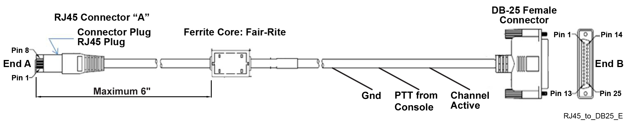
The following table provides additional information for the cable from the 4W MLC 8000 VGU to the MC2500 console.
| VGU Port 1 | MC2500-P1 | Plug-P2 | Plug-P4 | |||||
|---|---|---|---|---|---|---|---|---|
| Pin No. | Signal | Wire Color | Pin No. | Signal | Pin No. | Signal | Pin No. | Signal |
| 1 | Audio Out+ | White/Orange | 12 | +RX_Port1 | ||||
| 2 | Audio Out- | Orange | 25 | -RX_Port1 | ||||
| 3 | Audio In + | White/Blue | 11 | +TX_Port1 | ||||
| 4 | Audio In - | Blue | 24 | -TX_Port1 | ||||
| 5 | Channel Active | White/Green | 1 | E1 of OPTO coupler U2 | ||||
| 6 | PTT from Console | Brown | 3 | I/O Relay 1 NO Normally Open | ||||
| 7 | 5V | Green | Not connected | Not connected | ||||
| 8 | VGND | White/Brown | 13 | GND | 1 | I/O Relay 1_common | ||
NoteAll four inputs and all four outputs on the MC2500 are configurable using the RSS/CPS software.
| VGU Port 2 | Plug-P3 | |||||
|---|---|---|---|---|---|---|
| Pin No. | Signal | Wire Color | Pin No. | Signal | Notes | |
| 1 | Audio Out+ | White/Orange | Not Connected | |||
| 2 | Audio Out- | Orange | Not Connected | |||
| 3 | Audio In+ | White/Blue | Not Connected | |||
| 4 | Audio In- | Blue | Not Connected | |||
| 5 | Channel Active | White/Green | Not Connected | |||
| 6 | REPEAT_ON/OFF | Brown | 3 | Takeover1_NO Normally Open | Repeat On/Off | |
| 7 | 5V | Green | Not Connected | |||
| 8 | VGND | White/Brown | 1 | Takeover1-Common |