I did these mods without a schematic so I have renamed the two capacitors
needing changing using my own nomenclature as C1 and C2.
Parts needed:
I used standard 0805 style chip capacitors such as Panasonic 50 volt NPO chip
caps which are available from Digikey. These are DigiKey / Panasonic
parts in the PCC series. I used these as they are the most temperature stable
parts available. See the note at the end of this document about using the
alternate parts for C1 and C2. DIGIKEY part numbers for components used are as
follows:
C1 = Panasonic PCC080CNCT-ND 8pf, alternate = PCC070CNCT-ND
7pf
C2 = Panasonic PCC180CNCT-ND 18pf, alternate = PCC070CNCT-ND 15pf
Data
taken after several conversions shows that C1 =7.5 pf and C2 16 pf is perfect to
cover the entire band.
Before performing any of the steps below, first, using Motorola RSS
P200LB.EXE, read the original radio and save the original codeplug.
Confirm that it is a 42 to 50 MHz split radio. You must use RSS, P200LB.EXE
and not standard MT1000 RSS for the low band radios. If the radio you have is
not in the 42 to 50 MHz split, then stop right now as the mods to take a 36 to
42 MHz split to either 6 meters or 10 meters are more complex and still being
documented or worked on at this time. However; I have successfully moved a 36 to
42 MHz split MT1000 to the 10 meter ham band with great results but this is
still being documented as there are numerous receiver pre-selector changes.
Taking the radio apart:
- Open the MT1000 up by removing the two back cover screws and four bottom
screws. Two of the bottom screws hold the battery plate, these are the longer
BLACK screws. The other two screws are smaller and silver colored and they
hold the front cover on. Don't remove the screws holding the battery contacts.
- Pull the front cover away from the back section and disconnect the speaker
flex cable.
- Pull the radio away from and out of the Lexan case by grasping the antenna
and pulling away from the Lexan case.
- Remove the controller module (this is the large metal module in the center
of the radio) away from the main RF board by removing the four side screws and
gently pulling the two top connectors off while gently pushing on the two
bottom connectors (the connectors which attach to the VCO) at the same time to
free the controller board from the main board. Don't pull the controller out
very far at this time as there is a flex connector on the back.
- Carefully pull the controller up and slightly away from the main RF board.
Next carefully remove the back flex cable from the controller module. Place
the controller module aside.
- Turn the radio over so the back metal shield/cover is facing up and remove
the four screws securing the shield to the module.
- Look towards the bottom with the back shield removed and locate two screws
securing the VCO module; they are the only two screws near the bottom of the
radio module. Remove these screws. See Photo 1.
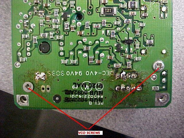
Photo
1, VCO hold down screws
Desoldering the VCO module from the main RF
board:
- Using a solder sucker or some de-soldering wick, remove the solder from
the 11 pins shown in Photo 2 and pull the VCO module away from the Main
Printed circuit board.
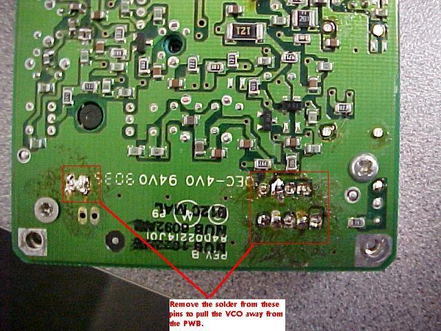
Photo
2, unsoldering VCO from main board
- Once the VCO is removed from the main RF board, pull the snap-on piece of
the three-piece VCO cover off and then pull the top metal cover off of the VCO
module (sorry I don't have picture of this step and my radio is back together
so I can't supply a picture, but the metal covers of the VCO are obvious so
this should not be a problem).
- Referring to Photo 3, desolder the pins from the controller part of the
VCO module so that the RF section of the VCO module can be separated. Pull the
RF section of the VCO board up and away from the remaining metal cover. The
result should be the RF VCO section in Photo 3. Your inductors on the left
side of the VCO may look different from those in my picture but this is not
important here.
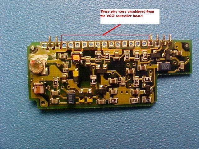
Photo
3, VCO RF board removed from VCO controller board
- Refer to Photo 4. Remove the capacitor at the location labeled C1 and
replace it with a 0805 case style 8pf chip capacitor. See the note in Radio
Programming step 7 below for alternate cap values.
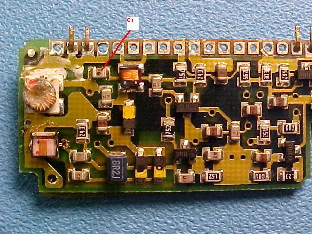
Photo
4. C1 location. Remove and replace with an 8pf NPO chip capacitor
- Refer to Photo 5. Remove the capacitor at the location labeled C2 and
replace it with a 0805 case style 18pf chip capacitor. See the note in Radio
Programming step 7 below for alternate cap values.
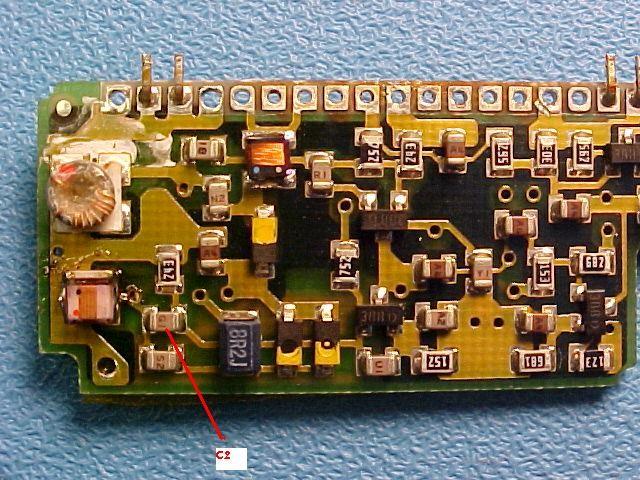
Photo
5. C2 location. replace with an 18pf NPO chip capacitor
- Re-assemble the VCO in reverse order and solder it back in to the main RF
board. Put the VCO module hold down screws back in.
- Re-assemble the controller module to the main RF board being sure to place
the back flex cable on first, then slide the two bottom VCO connectors on and
drop the controller into the Main RF board while carefully attaching the two
top connectors to the controller module.
- * * * * * ADDITION * * * * * 10-March-2008 * * * * *
Some people have
reported problems making the radio lock after the conversion and with the
display radios they have reported an error 88.
As a result you will need to
ground the PLL lock detect line prior to programming.
Lock detect is the
right most pin on the left most 7 pin connector going to the VCO module. This
is the connector closest to the speaker mic flex cable.
Simply connect
up a 1 inch piece of jumper wire from pin 7 of this connector and solder the
other end to the shield covering the RF/controller board.
- Re-assemble the covers and the case to put the radio back together.
Radio Programming:
- Start the RSS, open up a copy of the saved codeplug and change all
frequencies to 49.XXX Mhz where XXX is the actual frequency information to the
right of the decimal point of your desired frequencies. For example if channel
1 is 52.525 Mhz enter this as 49.525. If channel 2 for example is 52.56
receive and 52.06 transmit enter as 49.560 receive and 49.060 transmit.
- Enter in all CTCSS tone information and all other desired information into
the codeplug and save the codeplug to disk under a new name (i.e. do not wipe
out your original commercial band code plug archive). Exit the RSS.
- Start up your favorite hexadecimal file editor program and use it to open
the codeplug file. Look for your frequencies. They are very visible as decimal
values and not in hexadecimal format. They are in order of receive frequency
first then the transmit frequency. They should be obvious as viewed in the hex
editor. For the examples above you should see something
like:
0101...49525...49525...0202...49560...49060 etc. It's actually pretty
easy to find your way around a hexadecimal editor so I won't get into it
anymore than this.
- Change the 49 MHz part to your desired MHz such as 52 etc., do this for
all the programmed channels and save the codeplug, then exit the hex editor.
- Go back to P200LB.EXE and look at each channel to ensure the TX and RX
frequencies are correct. Use the channel up/down commands F4 and F3 but do not
move the cursor to the frequency entry field otherwise the RSS will try and
bring them back into the correct split. If there are any errors then fix them
now. You will need to reset the frequencies back to 49.XXX if there are any
errors in tones and other items and start over.
- If all the values in the codeplug are OK, then program the radio and check
each transmit and receive frequency on a service monitor (or equivalent test
equipment) to confirm all frequencies are working properly.
- I only needed transmit up to 53 MHz and receive up to 53.3 so this was the
extent of my testing. If you need to go higher in frequency with your TX or
you find your radio unlocking at the high end of the band on receive, then the
alternate values of capacitors C1 and C2 should be used.
Troubleshooting::
If you have any problems making the radio lock after the conversion you will
need to ground the lock detect line.
This step is Especially important if you converted the using an earlier
document which left out grounding the lock detect line before reprogramming.
The failure will be either the radio not locking on any frequency or with a
display radio and error 88 being displayed.
Lock detect is the right most pin on the left most 7 pin connector going to
the VCO module. This is the connector closest to the speaker mic flex cable.
Simply connect up an ~1 inch piece of jumper wire from pin 7 of this
connector and solder the other end to the shield covering the RF/controller
board.
If you tried to program a radio with a modified codeplug with error 88
displayed on a display radio you may have screwed up the radios internal tuning
values.
To fix this simply create a codeplug for the correct model/version of radio
that you have and enter in all frequencies of 49.99 MHz for tx and rx and
program this codeplug in the radio.
Next confirm that the radio is working on these channels and if so read this
codeplug out and save it to disk and then use this codeplug that you just read
out to hexedit in your 6 meter channels and it should fix any corrupted internal
tuning values.
Back
to the top of the page
Up one
level
Back to
Home
This page originally posted on Thursday
26-Oct-2006
Photographs and article text © Copyright 2006 by Mike May
WB8VLC/7.
Hand-coded HTML © Copyright 2006 by Robert Meister WA1MIK.
Date
of last update © Copyright 2006 by Repeater-Builder.Com
This web page, this web site, the information
presented in and on its pages and in these modifications and conversions is ©
Copyrighted 1995 and (date of last update) by Kevin Custer W3KKC and multiple
originating authors. All Rights Reserved, including that of paper and web
publication elsewhere.
