Install HiperMAX
SDR Blade
|

|
Danger of electrostatic discharge!
Static electricity can harm delicate components inside the shelf. An ESD
wrist strap must be worn before exchanging any part or electric component!
The ESD wrist strap terminal (4 mm banana jack) is located at the upper
front side of the shelf. |
Note: For instructions on board
insertion removal and replacement see Board
Insertion/Removal/Replacement
Note: When populating a 5 slot
shelf with blades Slot 3 should be used for the primary and slot 4 for
the secondary. When populating a 14 slot shelf with blades Slot 6 should
be used for the primary and slot 9 for the secondary. All blades should
use firmware 1.1.7 or later.
Note: All un-used slots should
be fitted with blanking plates - this is required for good EMC performance
and to reduce risk of inadvertent shorting on the installed PCBs.
The SDR blade is designed to plug into an ATCA chassis. The SDR’s architecture
is based on configurable elements to allow for changes in specification
i.e. software defined radio.
The SDR blade transports data over a fibre optic connection to the transceiver
using OBSAI RP3-01 interface running at 768Mbps for the SCRT and 3.072Gbps
for the MCRT.
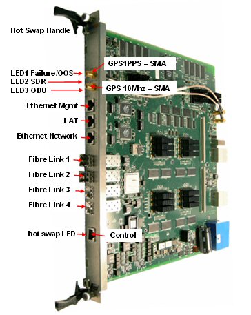
SDR Blade Front panel
|
Item |
Description |
|
ATCA – hot swap handle |
See Board Insertion/Removal/Replacement |
|
ATCA – hot swap LED H/S |
Once the extraction levers are released a flashing blue LED indicates
card de-activation requested.
Blue solid on indicates card de-activated and now safe to remove. Allow
30 seconds to close file systems. |
|
ATCA – LED1 Failure/OOS |
Out of Service LED (Red). Off
during normal operation. On when OOS. |
|
ATCA – LED2 SDR |
Long Blink: 900ms on, 100 ms off - indicates the SDR application is
initialising (similar to the blue LED behaviour - which relates to IPMC
state)
Short Blink: 100ms on, 900 ms off - indicates the SDR application is
terminating (irrespective of reason for the termination)
On: 100% illuminated, indicates the SDR application is up and running
Off: The SDR application has terminated |
|
ATCA – LED3 ODU |
On Green: All SCRTs attached to the blade are OK,
Off: SRCT not OK. |
|
LAT –
RJ45 RS-232 |
Used for LAT access.
1 Sys-Rx from PC
2 Sys-Tx to PC
3 Gnd
4 IPMC_Tx to PC
5 IPMC_RX from PC
6 Gnd
7 MAC-Tx to PC
8 MAC-RX from PC
The serial console default configuration is:
57600 baud: 8
data bits: 1 stop bit: no parity |
|
Ethernet Management |
RJ45 10/100 Ethernet port |
|
Ethernet Network |
RJ45 10/100 Ethernet port |
|
Control |
RJ45 RS232 to setup and control the GPS (Standard CAT 5 pin to pin patch
cable) |
|
GPS 10Mhz – SMA |
10MHz sinewave GPS signal from external GPS. 50 ohms |
|
GPS 1PPS – SMA |
1 PPS TTL,
50 ohms |
|
Fibre link 1 |
Plug in SFP ( Small Form-factor Pluggable) transceiver. |
|
Fibre link 2 |
Plug in SFP transceiver. |
|
Fibre link 3 |
Plug in SFP transceiver. |
|
Fibre link 4 |
Plug in SFP transceiver. |
The ATCA shelf needs to be populated in the
following order
1st SDR Slot 3
2nd SDR Slot 4
3rd SDR Slot 5
4th SDR Slot 1
5th SDR Slot 2
Install
On successful completion of this process, the SDR board will be
inserted into the correct
slot in the ATCA rack as specified by the job sheet.
connected to the 1PPS and
10MHz signals from the GPS module if specified to do this by the job sheet.
connected to manage the
GPS module if specified to do this by the job sheet.
configured with Base Station
ID (BSID) as specified in the job sheet.
configured with network
parameters as specified in the job sheet.
configured to send events
to the designated Netspan server as specified in the
job sheet.
configured to send and
receive network traffic from either an external switch or a switch which
is plugged in and configured in the ATCA rack as specified by the job
sheet.
connected to an external
Ethernet switch if specified by the job sheet.
connected to one or more
SCRTs as specified by the job sheet. Communications between SDR blade
and the SCRTs will be verified.
manageable from the Netspan
server specified by the job sheet.
Job Sheet
Prior to commencement of this procedure, the installer should have a
job sheet available. This should include the following information:
BS location and ATCA rack
identity
Whether the system is required
to be locked to a GPS timing reference.
Whether the SDR is to be
a Primary Master, Secondary Master or a Slave. This information will be
mapped to the ATCA rack slot number by this procedure.
A BSID is required for
each SDR Blade. This should be in a format xxxxxx:xxxxxx where x is a
decimal digit.
The mapping of SCRT ID
to Obsai port ID on the SDR blade.
Network configuration information
for the SDR blade. This shall include the following information for the
front panel and the backplane.
Traffic Port : Defines
whether traffic is via the front panel of the "SDR blade", "Primary
Backplane" or "Secondary backplane".
IP Address :
Should
only be set if "Management
IP Mode" is set to "Static IP Address" See
below for "Management IP Mode" parameter.
Netmask :
Should
only be set if "Management
IP Mode" is set to "Static IP Address" See
below for "Management IP Mode" parameter.
Default Gateway :
Should
only be set if "Management
IP Mode" is set to "Static IP Address" See
below for "Management IP Mode" parameter.
Management VLAN :
Specified
as either "Untagged" or "Tagged"
Management VLAN Tag :
Should
only be set if "Management VLAN" is set to "Tagged"
Management IP Mode :
Specified
as "Static IP Address" or "Obtain IP Address via DHCP"
Ethernet Mode :
Specified
as "Autonegotiate" or "Fixed"
Ethernet Rate :
Need only
be configured if "Ethernet Mode" is set to "Fixed".
Specified as "10M" or "100M".
Ethernet Duplex :
Need only be configured if "Ethernet Mode" is set to "Fixed".
Specified as "Full" or "Half"
Read Only Community :
This should be specified to the same value as in Netspan's Discovery Parameters. (Found
under "Server" on Netspan's left hand panel).
Read Write Community :
This should be specified to the same value as in Netspan's Discovery Parameters. (Found
under "Server" on Netspan's left hand panel).
SNMP Port Number : This
should be specified to the same value as in Netspan's Discovery Parameters. (Found
under "Server" on Netspan's left hand panel).
IP Address : This specifies
Netspan's
IP address (Found under "Server Global Configuration" which
is under "Server" on Netspan's left hand panel).
Community : Normally specified
to the same value as for "Read Only Community"
Port Number : Normally
specified to a value of 9023.