HiperMAX is a high-performance modular system based on the Advanced Telecom Computing Architecture (ATCA) equipment practice, consisting of:
ATCA shelf with 5 or 14 slots
Dual redundant ATCA shelf controllers
One or more SDR boards, executing the WiMAX PHY and MAC layers.
Masthead-mounted radio transceivers: single channel radio transceiver (SCRT) or future variants. See Single Channel Radio Receiver.
External antennas, for use with SCRT
Optional Ethernet switch blade
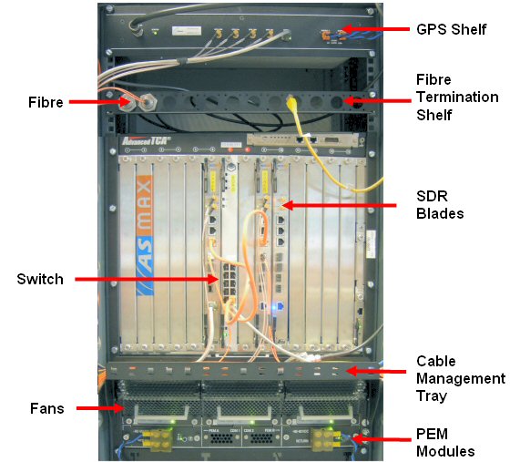
The HiperMAX BS consists of an indoor unit with outdoor radio and antennas. The indoor boards are housed in a 14-slot dual star ATCA chassis for HiperMAX configurations. 5-slot ATCA chassis are available for smaller systems. The ATCA chassis is design to mount directly into a 19 inch rack. Brackets are required to mount in an ETSI rack. The 14slot chassis is 13U high. A GPS unit and antenna provide an accurate frequency reference for the Base-station in order to ensure high radio frequency stability and also provide synchronisation between base-stations in TDD networks.
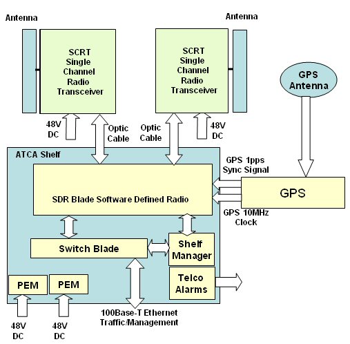
HiperMAX Schematic
13U ATCA equipment chassis with 14 slot shelf/backplane powered from an external -48vdc supply.
The backplane provides 12 payload slots for HiperMAX SDR blades, 2 slots for Ethernet switch blades and 2 dedicated shelf manager slots.
The chassis is equipped with:
- 2 front power entry modules
- 3 hot swap fan trays
- 1 ATCA shelf manager
- shelf alarm panel
- 13 front blanking panels fitted in vacant shelf slots
- 1 full rear blanking panel
- air filter
The two central slots are reserved for Ethernet Switch blades, (or future functions). The remaining 12 slots may be occupied by SDR blades. See Install 14-slot ATCA Shelf
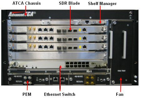
The 5 slot chassis uses 6U ATCA equipment chassis with 5 slot shelf/backplane powered from an external -48vdc supply.
The backplane provides 3 payload slots for HiperMAX SDR blades, 2 slots for Ethernet switch blades and 2 dedicated shelf manager slots.
The chassis is equipped with:
- 2 front power entry modules
- 1 hot swap fan tray
- shelf alarm panel
- 4 front blanking panels fitted in vacant shelf slots
- 1 full rear blanking panel
- air filter
Note: The 5-Slot ATCA shelf does not include a redundant fan. If the fan fails, the whole shelf will shut down after a short period of time. For full redundancy support (including fans), use the 14-slot chassis.
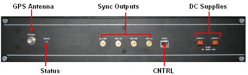
The GPS Receiver GPSR-R-19-1 consists of a 19” rack mounted enclosure housing a GPS receiver module and a signal distribution board. The unit outputs two 10MHz and 1pps clock synchronisation signals. It is powered by external 48V supply with redundancy.
The GPS receiver provides an accurate frequency derived from the Coarse Acquisition Link 1 signals transmitted by the Navstar Global Positioning System (GPS) satellites. The GPS input is used as the reference for the tracking function. When no valid input reference is available, the GPS receiver enters hold-over mode and holds its output frequency to the one that was available just before the loss of the input.
The receiver:-
supplies ITU-T G.811 references with valid GPS signal,
Monitors the status of the reference input signal (GPS),
Operates as a standby reference clock in hold-over mode if synchronisation inputs has decreased in quality or failed,
Communicates by a serial port (RS-232C) with the SDR blade for alarm reporting and equipment control.
The SDR blades' architecture is based on configurable elements, allowing implementation of a software defined radio, which ensures changes in specification can be adopted without the need to change the basic hardware construction. Using the approach based on configurable elements, the base station can be upgraded from the 802.16-2004 OFDM “Fixed WiMAX” system profile to the 802.16e-2005 OFDMA “Mobile WiMAX” system profile through the simple process of upgrading the system software. The PHY processing is implemented using picoChip™ technology, and the MAC is implemented within two PowerPC processors. The SDR board performs the baseband processing and frames I/Q and control signals into OBSAI RP3-01 to interface to the outdoor radio transceiver.
There are four fibre ports per SDR blade. Each transceiver is connected to one port via a fibre optic cable. Currently two OBSAI links can be active at any time, the other two links are for redundancy. There can be up to 12 SDR blades per shelf in 14-slot configuration. There is a separate power feed for each transceiver.
The Ethernet switch cards located in the two centre slots. It is housed on a single ATCA blade used to consolidate Ethernet traffic from all SDR blades in an ATCA chassis. This single network Gigabit Ethernet connection is then available for presentation into the backhaul equipment, or IP core network. It can also be configured such that management traffic is presented on a physically separate Ethernet port.
This solution is a platform for full redundancy switching across the ATCA backplane and removes the need for unreliable patch connections from SDRs to a separate switch. It is also managed by Netspan as an integral part of the HiperMAX base station. It is aimed at “carrier class” operators wanting a fully integrated multi-sector solution.
For smaller systems, a separate rack mount Ethernet switch can be used connected to the SDR Blades via their front panel Ethernet connections. This is a low cost alternative to the ATCA Ethernet switch for small HiperMAX configurations and as such, has the following limitations:
• Capacity limited to support up to 3 SDRs
• Not managed through Netspan
• Single mains PSU only
• Ethernet patch cables required connecting to SDR front panels (not supplied)
• Not suitable for redundant configurations