For TDD and smart antenna operation the base stations need to be locked to GPS timing. The ATCA shelf has a synchronisation clock interface that is connected to all 14 blades in the Shelf.
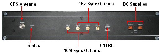
The GPS reference is generated by the GPS shelf. Each SDR blade locks onto the 10MHz signal to align with the GPS clock. The GPS module outputs 10MHz(10M) and 1pps (1Hz) signals.
The SDR blades are able to operate in stand alone mode and have a GPS input on the front panel. In order to allow clock redundancy, the GPS signals are fed to two blades. The SDRs that have GPS connected are selected via Netspan – one is selected as the master the other as standby. The master SDR blade drives the 10MHz GPS clock signal onto the backplane signal CLK3A. The standby blade drives the GPS clock onto CLK3B. Each SDR card in the system monitors CLK3A and CLK3B. One of these is selected to drive the boards PLL and derive the clocks. If one of the SDR boards fail or the GPS is unplugged or the blade is removed, the SDR blades will then switch to the other clock source. If both CLK3A and CLK3B fail then the PLLs free run.
|
Supplied Parts |
Quantity |
|
2U 19" GPS Receiver |
1 |
|
SMA to SMA Sync Cables |
4 |
|
RJ45-RJ45 Control Cable: Standard CAT5 Pin to pin patch cable |
1 |
|
|
|
|
Other Required Parts |
|
|
GPS Antenna (choose from) |
TA-200 Antenna for feeder installation up to 35m from SDR |
|
Trimble Bullet 3 Antenna for feeder installation up to 60m from SDR | |
|
Antenna Feeder Cable (choose from) |
RG58 For runs up to 20 metres |
|
RG213 For runs up to 60 metres | |
|
Surge Protector |
Polyphasor or simular |
The GPS shelf is currently available as a standard 2u 19inch shelf. It is usual to place the GPS receiver at the top of the rack.
Note: When running cables (Ethernet; OBSAI; GPS Control; and SMA cables for GPS 1PPS & 10MHz) from the front of all blades (SDR and/or Switch), Shelf Manager and SAP it is important that the cables run directly up and down the length of the card and not across the face of other cards. This is important in order to ensure that individual blades can be inserted and removed without interfering with the cabling to other blades in the shelf. When running any cable along the ATCA shelf cable management tray it is important to leave enough slack in the cable to allow the raising and lowering of the cable management tray in order to allow access to the fan modules and air filter tray.
Secure the shelf in the rack using screws into the cage nuts (Screws and nuts not provided by Airspan.)
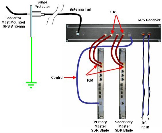
Run two 1.5mm Blue and Black DC feeds and returns from the 48 volt breakers to the GPS unit.
Terminate and connect on the -48V to the A and B terminals.
Connect 10M and 1Hz using the jumper cables provided to the corresponding terminals on the primary master.
Connect 10M and 1Hz using the jumper cables provided to the corresponding terminals on the secondary master.
Connect the CNTRL cable from the GPS shelf to the CNTRL port on the primary master.
Run the cable from the Antenna to the GPS Shelf and attach to the GPS Antenna port and attach to the GPS Antenna. Neatly tie any excess cable (see Cable Ties).
Connect the antenna feeder cable to the shelf.