Conventional Channel Cluster Tree
A channel cluster must be defined on a newly deployed system. The configuration of the entire channel cluster starts with connecting, using the external LAN port, to each device to provide it with the IP address. Then the MLC 8000 Configuration Tool is used to build the entire channel cluster and to configure each device. When the MLC 8000 Configuration Tool is used to select a particular channel cluster, the associated channel cluster tree appears. Only one channel cluster can be open at a time and only one channel cluster tree appears in the channel cluster tree display area. Each device that is added to the channel cluster can belong to only one channel cluster.
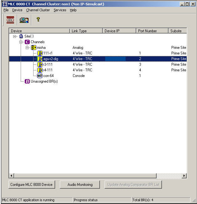
Display of Channel Cluster Tree Window Title
After a channel cluster is created, the MLC 8000 Configuration Tool displays the channel cluster name and type at the top of the main screen window. Both the name and type are specified during the process of creating the channel cluster.
Structure of the Channel Cluster Tree
Adding a comparator (MLC 8000 Analog Comparator (VGU), GRV 8000 Digital Comparator, GCM 8000 Digital Comparator, or Mixed Mode Comparator) to the channel cluster causes the device to appear under the Channels branch. A maximum of four comparators can be associated with a channel cluster. Each comparator in the cluster can be connected to up to 64 BRs as long as the total number of AGU ports associated with all the VGUs in a single channel cluster does not exceed 64 AGU ports. If an AGU port is connected to a comparator, then it must be a comparator from the channel cluster. Each VGU is displayed with a console (even if in the real system the console does not exist). This association is for practical reasons, to enable audio monitoring on the link between the VGU to the console. Adding an MLC 8000 Subsite Link Converter (AGU) to a channel cluster causes the four ports of this AGU to display under the Unassigned BR branch initially. After each port of the MLC 8000 Subsite Link Converter (AGU) is associated with a particular channel, the base radios connected to the port display as attached to the associated comparator (analog, digital, or mixed mode). You can right-click the comparators and base radios in the channel cluster tree and then a submenu is opened to allow you to configure that device. You can monitor the console by clicking it and then selecting the audio monitoring button at the top of the display.Display of Comparators in the Channel Cluster Tree
The channel cluster tree displays three types of comparators:
- Analog: MLC 8000 Analog Comparator (VGU)
- Digital: GCM 8000 Digital Comparator or GRV 8000 Digital Comparator
- Mixed Mode: MLC 8000 Analog Comparator (VGU) and GCM 8000 or GRV Digital Comparator working together as one logical comparator
Analog Comparator: An analog comparator appears in the channel cluster tree by its name attached to the voter icon. The voter icon appears as follows:

Digital Comparator: A digital comparator appears in the channel cluster tree by its name attached to the voter icon. A digital comparator appears in the channel cluster tree of the MLC 8000 Configuration Tool and is also counted as one of the comparators of the channel cluster. However, the GCM 8000 and GRV 8000 digital comparators cannot be configured using the MLC 8000 Configuration Tool.
Mixed Mode Comparator: A mixed mode comparator appears in the channel cluster tree as its name attached to the voter icon. Even though there is just one symbol for a mixed mode comparator, the symbol stands for two comparators, the digital GCM 8000 or GRV 8000 comparator and the analog MLC 8000 comparator.
Display of MLC 8000 Subsite Link Converters (AGUs) and their Base Radios in the Channel Cluster Tree
MLC 8000 Subsite Link Converters (AGUs) are omitted from the channel cluster tree display. Instead, the channel cluster tree displays base radios (BRs) connected to the comparators through AGU ports. The AGU port is then "associated” with the VGU. The IP address for the MLC 8000 Subsite Link Converter (AGU) appears in the IP Address column for each base radio. A base radio is represented in the channel cluster tree with its name and the following base radio icon:

When the base radio icon is displayed without a “V” included in the icon, it is not yet associated with an MLC 8000 Analog Comparator (VGU). The base radio icon can be displayed with a blue “V” inside the icon. This display indicates that the MLC 8000 Subsite Link Converter (AGU) is connected to the MLC 8000 Analog Comparator (VGU), and both show this association in their configuration. This display does not indicate a problem. This icon can also be displayed with a red “V” inside the icon. If this display appears, it indicates a problem with the configuration between the MLC 8000 Subsite Link Converter (AGU) and the MLC 8000 Analog Comparator (VGU). For example, the AGU is configured to say that it is associated with a particular VGU, but the VGU configuration does not show the association. See procedure Resolving a Configuration Problem Indicated by a Red “V” in the Base Radio Icon.
Displayed Color of Icons in Channel Cluster Tree
Active base radios and MLC 8000 Analog Comparators (VGUs) display with a yellow icon. If the MLC 8000 Analog Comparator (VGU) is active, mixed mode comparators display with a yellow icon.. The activity status of the digital comparator is not known to the MLC 8000 Configuration Tool and is not reflected in the color of the mixed mode comparator icon. Digital comparators display with a white icon because their activity status is not available to the MLC 8000 Configuration Tool.
Channel Cluster Devices Sorting
With the allowance of 64 MLC 8000 Subsite Link Converters (AGUs) per MLC 8000 Analog Comparator (VGU), you must use the scroll bar to view all the devices in the channel cluster. By clicking the Device column title, the base radio names of all base radios associated with the VGU are sorted alphabetically. Each click on the Device column title performs a rotation between sorting in ascending or descending order.
Sorted voters are displayed in the following order:
- First, all analog channels of the channel cluster with their associated sorted nodes are displayed.
- Next, all digital channels of the channel cluster with their associated sorted nodes are displayed.