Configuring an MLC 8000 Subsite Link Converter for a Non IP Simulcast System
Prerequisites:
- The MLC 8000 Configuration Tool is operational. See procedure Opening the MLC 8000 Configuration Tool.
- The system to which this MLC 8000 Subsite Link Converter is being added is a non IP simulcast system.
When and where to use:
Use this procedure to modify the configuration of an MLC 8000 Subsite Link Converter (AGU) for a Non IP Simulcast system.
ImportantParameters displayed with the letter [R] after the parameter name on the configuration screens require a device restart for saving the new parameter value in the device.
Procedure:
- If an incorrect channel cluster is open and displayed on the main screen of the configuration tool, close it by clicking . Click and select the channel cluster file to open from the system folder. Click OK.
The channel cluster selected opens and the channel cluster tree is displayed on the MLC 8000 Configuration Tool main screen.
- From the channel cluster tree, right-click the MLC 8000 Subsite Link Converter you want to configure and select , or select the MLC 8000 Subsite Link Converter you want to configure and then click the Configure MLC 8000 Device button or select from the menu at the top of the screen.
The Modify Device Configuration window appears.
Modify Device Configuration Window – General Properties Tab for an AGU in a Non IP Simulcast System 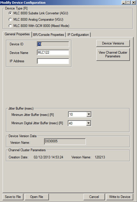
- Verify that in the Device Type field, MLC 8000 Subsite Link Converter (AGU) is selected.
If this field is not already selected and you select it, a prompt is provided asking if the device type should be changed. If the device you want to configure is an MLC 8000 Subsite Link Converter (AGU), click Yes.
- If the general properties-related fields are not displayed, click the General Properties tab to display them.
The fields associated with the General Properties tab display, including the device ID.
- Enter a device name of up to 19 alphanumeric characters in the Device Name field. This name should be a user-friendly name that allows easier identification of the MLC 8000 Subsite Link Converter within the screens of the MLC 8000 Configuration Tool.
NoteIf you change the device name, the MLC 8000 Subsite Link Converter is restarted in order to implement the new value.
- For a digital system, skip this step and continue with the next. For systems that are not digital systems, enter the minimum jitter buffer length (in msec, multiples of 10) in the Minimum Jitter Buffer (msec) field. The default value for this field is 20 msec.
NoteThe default minimum jitter buffer of 20 msec is based on the IP Transport Jitter of 10 msec. It is (2 * IP Transport Jitter), rounded up to the nearest tenth because the Minimum Jitter Buffer resolution is in multiples of 10. Enter a value in this field only if your MLC 8000 Subsite Link Converter is in an analog or mixed mode system (including IP Simulcast systems) or if the AGU has at least one port that is connected to a base radio either by 4–wire or by a mixed mode link.NoteIf you change the minimum jitter buffer length, the MLC 8000 Subsite Link Converter is restarted in order to implement the new value.
- Enter a value of 0 msec to 100 msec in the Minimum Digital Jitter Buffer (msec) field to specify the Jitter Buffer length (in msec) of the digital links at the MLC 8000 Subsite Link Converter. The default value for this field is 20 msec.
NoteIf this system is a digital system running in simulcast mode, the digital jitter buffer field should be set to 0. If this system is a non IP Simulcast digital system, this field should be set to (2 * IP Transport Jitter), rounded up to the nearest tenth because the Minimum Jitter Buffer resolution is in multiples of 10. This field (minimum digital jitter buffer) should be filled in only if this MLC 8000 Subsite Link Converter (AGU) is in a digital or a mixed mode system or if it has at least one port that is connected to a base radio either by V.24 or by a mixed mode link.NoteIf you modify the minimum digital jitter buffer length, the MLC 8000 Subsite Link Converter is restarted in order to implement the new value.
- Select the BR/Console Properties tab.
The BR/Console Properties fields appear and the corresponding Port ID is displayed.
Modify Device Configuration Window – BR/Console Properties Tab for an AGU in a Non IP Simulcast System 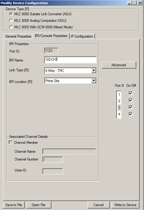
- Enter a base radio name of 0 to 19 alphanumeric characters in the BR Name field.
- Specify the link type using the drop-down list in the Link Type field.
NoteIf you change the link type, the MLC 8000 Subsite Link Converter is restarted to implement the new value.
- Specify the location of the device from the BR Location field drop-down menu. The options are Prime Site, a specific subsite, or Add Subsite. This name is the subsite name of the site at which the device is deployed or the system (prime) site. If the specific subsite does not appear in the drop-down menu, Add Subsite can be selected. Choosing Add Subsite causes the Subsite List window to appear; in this window, a specific Subsite ID should be selected by clicking it and then Modify Name for Subsite. After the desired subsite name is entered, click OK and then Apply. The subsite name then appears in the drop-down list in the BR Location field and can be selected.
NoteIf you modify the BR location, the MLC 8000 Subsite Link Converter is restarted to implement the new value.
- Select the port for which to do advanced configuration in the Port # field.
- Click Advanced.
The BR Advanced Configuration window appears for the particular port selected.
Modify Device Configuration Window – BR Advanced Main Tab for an AGU in a Non IP Simulcast System 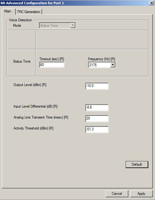
- Enter status tone timeout, a value from 3 to 65535 seconds, in the Status Tone Timeout (sec) field. The default value for this field is 60 seconds.
- Enter status tone frequency (2100 Hz, 2175 Hz, or 2325 Hz) in the Status Tone Frequency (Hz) field by selecting the desired frequency from the drop-down list. This field has a default value of 2175 Hz.
NoteIf you change the value of status tone frequency, the MLC 8000 Subsite Link Converter is restarted in order to implement the new status tone frequency value.
- Specify the output level in the Output Level (dBm) field. This field controls the average audio level. Allowable values are -20.0 to 0.0 dBm in 0.1 dB steps. The default value for this field is -10.0 dBm.
NoteIn 4-wire TRC links, the High Level Guard Tone (HLGT) is generated at 6 dB higher gain than the power level of the transmitted audio. The Function Tone (FT) is generated at -10dB in relation to the HLGT power. Low Level Guard Tone (LLGT) is generated at -30dB level in relation to the HLGT.
- Enter the input level differential in the Input Level Differential (dB) field. The default value for this field is -8.6 dB (assuming the level of status tone/ALMT is -13 dB). If the level of status tone/ALMT is different, set this field to be 4.4 dB above the status tone/ALMT level.
NoteInput Level Differential = Status Tone/ALMT Level Below Peak Audio + 4.4, where peak audio is at 100% deviation.
- Enter the analog line transient time in the Analog Line Transient Time (msec) field. The default value for this field is 20 msec.
NoteIf you change the value of analog line transient time, the MLC 8000 Subsite Link Converter is restarted in order to implement the change.
- Enter the threshold for the energy level detected on the 4–wire line in the Activity Threshold (dBm) field. Signals with a detected energy level below this threshold for the time specified in the Status Tone Timeout field are determined to be a disconnected line. The activity threshold has a default value of -51.3 dBm, and the range of allowable values is 0 to -78.0 dBm in 0.1 dB steps.
NoteThis field is used only when the status tone timeout field is set to 5 seconds or less.
- Click the TRC Generation tab.
The TRC Generation tab fields appear.
Modify Device Configuration Window – BR Advanced TRC Generation Tab for an AGU in a Non IP Simulcast System 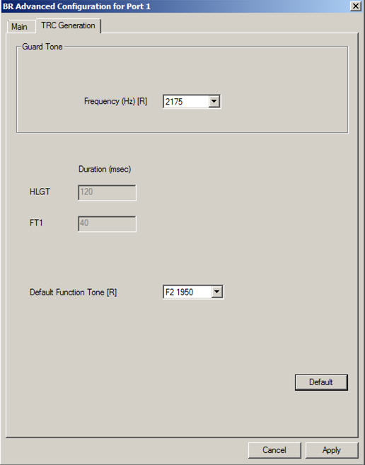
- Specify the default function tone using the drop-down list in the Default Function Tone field. Allowable values are F1 2050, F2 1950, F3 1850, F4 1750, F5 1650, F6 1550, F7 1450, F8 1350, F9 1250, F10 1150, F12 950, F13 850, F14 750, F15 650, F16 550, or F17 450.
- Click Apply.
The configuration changes are applied and the BR Advanced Configuration window closes.
- Repeat steps 14 through 20 for each MLC 8000 Subsite Link Converter port you want to configure.
NoteFor each port you want to configure, the respective On/Off field for that particular port must first be checked.
- If the IP address or the speed and duplex setting of the MLC 8000 Subsite Link Converter requires modification, select the IP Configuration tab. If not, continue with step 27.
The fields related to IP Configuration appear.
Modify Device Configuration Window – IP Configuration Tab for an AGU in a Non IP Simulcast System 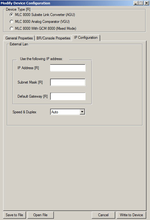
- Specify the IP addresses in the IP Address field.
NoteFor MLC 8000 devices implemented in ASTRO ® 25 systems, contact your system administrator for the appropriate IP address.
- Specify the address for the subnet mask in the Subnet Mask field.
NoteFor MLC 8000 devices implemented in ASTRO ® 25 systems, contact your system administrator for the subnet mask address.
- Specify the address for the default gateway in the Default Gateway field.
NoteFor MLC 8000 devices implemented in ASTRO ® 25 systems, contact your system administrator for the default gateway address.
- Use the Speed & Duplex field drop-down menu to choose Auto, 10 Mb Full, 10 Mb Half, 100 Mb Full, or 100 Mb Half.
- Select Write to Device to save the changes.
A dialog box appears to verify that the configuration changes should be applied.
- Select Yes.
The changes are applied to the configuration and the Modify Device Configuration window closes.