Configuring an MLC 8000 Subsite Link Converter for an IP Simulcast System
Prerequisites:
- The MLC 8000 Configuration Tool is operational. See procedure Opening the MLC 8000 Configuration Tool.
- The system to which this MLC 8000 Subsite Link Converter is being added is an IP Simulcast system.
When and where to use:
Use this procedure to modify the configuration of an MLC 8000 Subsite Link Converter (AGU).
ImportantParameters displayed with a letter [R] after the parameter name on the MLC 8000 Configuration Tool screens require a restart of the MLC 8000 Subsite Link Converter for saving the new parameter value in the device
Procedure:
- If an incorrect channel cluster is open and viewable from the main screen of the MLC 8000 Configuration Tool, close it by clicking . Click . Select the channel cluster to open from the System folder. Click OK.
The channel cluster opens and the channel cluster tree displays on the configuration tool main screen.
- In the channel cluster tree, right-click the MLC 8000 Subsite Link Converter (AGU) to configure and click Configure Device or select the MLC 8000 Subsite Link Converter from the channel cluster tree and then click the Configure MLC 8000 Device button or select from the menu on the top of the main screen.
The Modify Device Configuration window appears.
Modify Device Configuration Window – General Properties Tab for an AGU in an IP Simulcast System 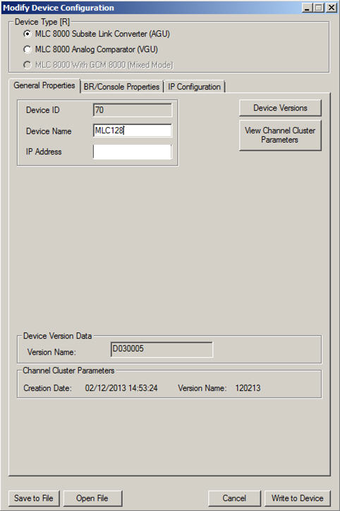
- Verify that in the Device Type field, MLC 8000 Subsite Link Converter (AGU) is selected.
NoteIf this field is not already selected and you select it, a prompt is provided asking if the device type should be changed. If the device you want to configure is an MLC 8000 Subsite Link Converter (AGU), click Yes.
- If the fields associated with the General Properties tab are not already displayed, click General Properties.
The fields associated with the General Properties tab display, including the device ID.
- Enter a device name of up to 19 alphanumeric characters in the Device Name field. This name is a user-friendly name that allows easier identification of the MLC 8000 Subsite Link Converter within the screens of the MLC 8000 Configuration Tool.
NoteIf you modify the device name, the MLC 8000 Subsite Link Converter is restarted to implement the change.NoteSet the minimum Digital Jitter Buffer value to zero.
- Select the BR/Console Properties tab.
The BR/Console Properties fields appear and the Port ID displays. The Link Type is also displayed and for an IP Simulcast system is set to 4W Ext. PTT (IP Simulcast). Neither the Port ID nor Link Type field can be modified.
Modify Device Configuration Window – BR/Console Properties Tab for an AGU in an IP Simulcast System 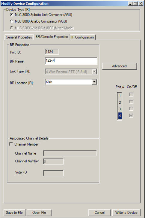
- Enter a base radio name of up to 19 alphanumeric characters in the BR Name field.
- Specify the location of the device from the BR Location field drop-down menu. The options are Prime Site, a specific subsite, or Add Subsite. This name is the subsite name of the site at which the device is deployed or the system (prime) site. If the specific subsite does not appear in the drop-down menu, Add Subsite can be selected. Choosing Add Subsite causes the Subsite List window to appear; in this window, a specific Subsite ID should be selected by clicking it and then Modify Name for Subsite. After the desired subsite name is entered, click OK and then Apply. The subsite name then appears in the drop-down list in the BR Location field and can then be selected.
NoteIf you modify the BR location, the MLC 8000 Subsite Link Converter is restarted to implement the change.
- Click Advanced.
The BR Advanced Configuration window appears.
Modify Device Configuration Window — BR Advanced Main Tab for an AGU in an IP Simulcast System 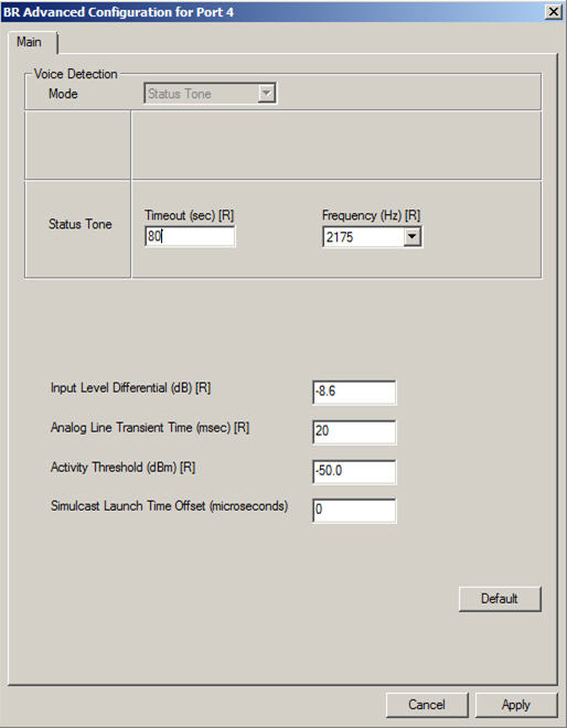
- Enter status tone timeout, a value from 3 to 65535 seconds, in the status tone section Timeout (sec) field. The default value for this field is 60 seconds.
- Enter status tone frequency (2100 Hz, 2175 Hz, or 2325 Hz) in the status tone section Frequency (Hz) field by selecting the desired frequency from the drop-down list. This field has a default value of 2175 Hz.
NoteIf you modify status tone frequency, the MLC 8000 Subsite Link Converter is restarted in order to implement the parameter change.
- Enter the input level differential in the Input Level Differential (dB) field. The default value for this field is -8.6 dB (assuming the level of status tone/ALMT is -13 dB). If the level of status tone/ALMT is different, set this field to be 4.4 dB above the status tone/ALMT level.
NoteInput Level Differential = Status Tone/Analog Link Monitor Tone (ALMT) Level Below Peak Audio + 4.4
- Enter the analog line transient time in the Analog Line Transient Time (msec) field. The default value for this field is 20 msec.
NoteIf you modify the analog line transient time, the MLC 8000 Subsite Link Converter is restarted in order to implement the change.
- Set the threshold for the energy level detected on the 4–wire line using the Activity Threshold (dBm) field. Signals with an energy level below this threshold for a tone using status tone timeout are determined as a disconnected line.
NoteThis field is used only when the status tone timeout field is set to 5 seconds or less.
- Specify the simulcast launch time offset in the Simulcast Launch Time Offset (microseconds) field. The default value for this field is 0 microseconds.
NoteSome values cause a restart of the device. The values that will cause a device restart are: 124, 249, 374,499,624,749, and 874. The constraint to use the subsequent value for launch time offset (difference in one micro second) will not harm audio quality. The MLC 8000 Configuration Tool will block configuring these values with a message similar to the following: Invalid Simulcast Launch Time Offset value entered! Offsets 124,249,374,499,624,749, and 874 microseconds are not allowed and will be replaced with the subsequent value.
- Click Apply.
The configuration changes are applied and the BR Advanced Configuration window closes.
- If the IP address or the speed and duplex setting of the MLC 8000 Subsite Link Converter should be changed, select the IP Configuration tab. If not, continue with step 23.
The fields related to IP Configuration appear.
Modify Device Configuration Window – IP Configuration Tab for an AGU in an IP Simulcast System 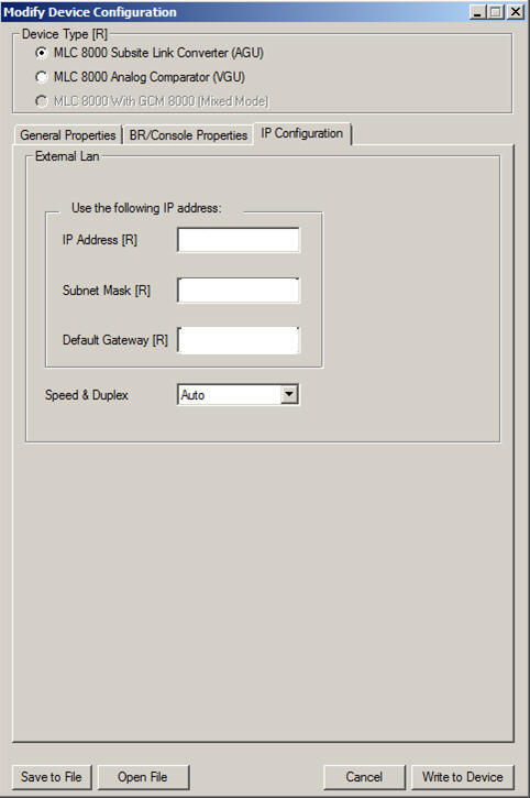
- Specify the IP addresses in the IP Address field.
NoteContact your system administrator for the appropriate IP address.
- Specify the subnet mask address in the Subnet Mask field.
NoteContact your system administrator for the appropriate subnet mask address.
- Specify the default gateway address in the Default Gateway field.
NoteContact your system administrator for the appropriate default gateway address.
- Set the Speed & Duplex field to Auto, 10 Mb Full, 10 Mb Half, 100 Mb Full, or 100 Mb Half using the drop-down menu.
- Select Write to Device to save the changes.
A window pops up asking if the current configuration should be applied.
- Click Yes.
The configuration changes are applied and the Modify Device Configuration window closes.