ASTRO 25 Digital-Only Simulcast Voting Subsystem Equipment Cabling
This section provides a high-level subsystem diagram and equipment cabling tables from the MLC 8000 device to other system devices. A port description table lists the system devices and refers to the device documentation for more information.
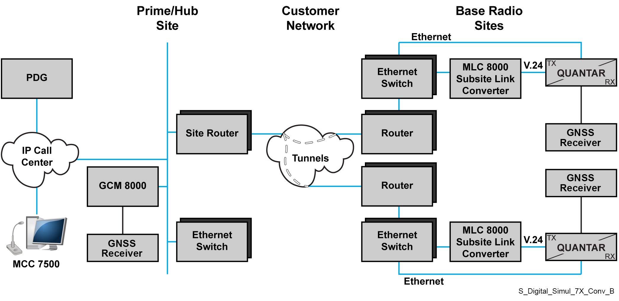
ImportantHigh-level diagrams are provided as examples only and are not to be used for system planning purposes. “GPS” in the diagram refers to a Simulcast Site Reference device. This service is now called Global Navigational Satellite System (GNSS).
NoteThe following table provides part numbers for cables that are orderable from Motorola Solutions. Create the remaining cables using the provided pinout tables. See
MLC 8000 Radio Ports Cabling.
| From MLC 8000 Subsite Link Converter (Subsite) | To Destination Device: | |||
|---|---|---|---|---|
| Port | Connector Type | Device | Connector Type | Description |
| External LAN PoE | RJ-45 | LAN Switch | RJ-45 | RJ-45–to-R-J45 one-to-one cable |
| VIP | RJ-45 | SDM3000 RTU | I/O Wiring Punch Block | MLC 8000 to SDM3000 RTU Cable |
Port Descriptions for ASTRO 25 Digital-Only Simulcast Voting Subsystem
| Device | Manual |
|---|---|
| MLC 8000 | See “MLC 8000 Ports” in the MLC 8000 Comparator Feature Guide. |
| LAN switch | See “HP Switches – Determining Port Connections in ASTRO 25 Systems” in the Ethernet LAN Switches Feature Guide. |
| SDM3000 RTU | See the Installation chapter “Connecting I/Os with Punch Blocks” sub-section and Appendix C “Pin Assignments” and “Punch Block Terminal Block Contacts” in the SDM3000 Site Device Manager User Guide. |
| GTR 8000 Base Radio | “Transceiver Ports – Front” in the RF Site Technician Guide. |