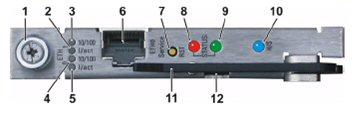
1. Fixing screw
2. ETH 1 Link/Activity LED (green) :
on = link,
off = no link,
blinking = link + activity
3. ETH 1 Speed (yellow) :
on = 100 Mb,
off = 10 Mb
4. ETH 0 Speed (yellow) :
on = 100 Mb,
off = 10 Mb
5. ETH 0 Link/Activity LED (green) :
on = link,
off = no link,
blinking = link + activity
6. ETH 0 Ethernet service connector
7. Reset push button
8. Shelf manager status LED (red) : red = out of service
9. Shelf manager status LED (green) :
on = in service, active,
blinking = in service, backup shelf manager
10. Hot swap LED (blue) :
on = board may be extracted,
long blink = initialising,
short blink = deactivating (hot swap requested but not ready),
off = board active, do not extract
11. Hot swap handle. Half pulled to initiate hot swap request sequence, and await the hot swap LED arriving at permanently on state. Thereafter, fully pulled to extract board
12. Hot swap switch. Activated by half pull of the hot swap handle. Directs whether hot swap is requested, or activation is requested.
Access to the shelf manager is via:
Shelf Manager serial connection (LAT): This Interface is on the CDM Tray and provides access to all shelf manager configuration tools except the web interface. It allows manipulation of the shelf manager at all levels including the boot prompt, Linux command line and the shelf manager command line interface.
Local IP address: provides access to all shelf manager configuration tools except boot prompt. environment variables. The ipaddress, netmask and gateway must be configured using the LAT connection before access is possible.
Network IP Access: provides access to all shelf manager configuration tools except boot prompt. environment variables. The ipaddress, netmask and gateway must be configured using the LAT connection before access is possible.
Communication with the shelf manager is either by:
Linux command line.
ARM boot environment.
Shelf manager command line interface.
or
Shelf manager web interface.
A managed HiperMAX shelf may be configured with either a single or dual redundant shelf managers.
Five possible configuration procedures exist.
For configuration details see 605-0000-837 HiperMAX Commissioning/ Shelf Manager Configuration
Configure a single shelf manager.
Configure dual redundant shelf managers.
For configuration details see 605-0000-840 HiperMAX System Maintenance/Shelf Manager Operations
Remove the redundant shelf manager.
Add a shelf manager to introduce redundancy.
Replace an unhealthy shelf manager.