
|
Mains Connector and 48V Connectors |
300N.cm |
|
OBSAI Connectors |
100N.cm |
|
TNC Connectors |
46-69N.cm |
|
Fibre Connectors |
1Nm |
|
LAT CAP |
Finger tight |
85V to 265V AC 47-63Hz Single Phase. The power input is via a plug and a 1m lead. The three conductors are as follows:
|
Connection |
All countries except USA Japan |
USA/Canada |
Japan |
|
Earth (Ground) |
Green/Yellow |
Green |
Red |
|
Neutral (Cold) |
Blue |
White |
White |
|
Live (Hot) |
Brown |
Black |
Black |
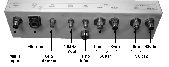
The Ethernet cable is connected to the SDR using a standard RJ45 connector protected by a harsh environment protective casing. For details of assembling protective casing see Ethernet Connection. Some versions have been shipped with Amphenol connectors, versions are now shipped with LTW connectors
This interface is used to provide 1 pulse /sec synchronisation between a HiperMAX-micro master SDR and a HiperMAX-micro slave SDR
A 1.5 metre connecting cable (terminated at both ends with a TNC connectors) is provided with a slave BS
This interface is used to provide 10MHz clock between a HiperMAX-micro master SDR and a HiperMAX-micro slave SDR.
A 1.5 metre connecting cable (terminated at both ends with a TNC connectors) is provided with a slave BS
Each SCRT is provided with a 3/10/30 metre 48 volt power cable terminated with a male connector at one end and a female connector at the other.
 Important
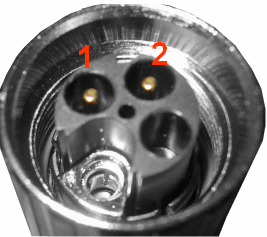
Note: The male connector attaches to the SDR and the female connector
attaches to the SCRT. It is important that the power connector is attached
at the correct end see illustration below or damage to the connector/equipment
will result.

Power connector cable termination for SDR end
Each SCRT is provided with a 3/10/15/30/100 metre optical fibre cable, ready terminated with optical connectors. Unscrew the protective dust cap and screw the fibre optic cable in place. Only remove the cap prior to installation and never leave the optical interface open withoit a protection cap.
Tighten to 1Nm using a calibrated torque wrench. Never exceed 2Nm as the optical interface may be damaged causing excess losses
When running cables care should be taken not to exceed
a force of 800N on the cable or connector. Do not kink cable or bend over
sharp edges.
