Performing Calibration for an MLC 8000 Analog Comparator for a TRC Console
Prerequisites:
The following prerequisites must be met before the MLC 8000 Analog Comparator (VGU) can be calibrated:- The MLC 8000 Configuration Tool is operational. See procedure Opening the MLC 8000 Configuration Tool.
The VGU has been configured.
A power meter is connected between VGU port 1 and the console table.
When and where to use:
Follow this procedure to calibrate the audio from a console to the VGU to get the optimum signal level in analog and mixed mode systems. You can perform this calibration on a console to VGU link before the VGU is associated with any base radios.
Use this procedure:Whenever you connect a console to the VGU for the first time
Whenever you replace a cable between the console and the VGU or between a CCGW and the VGU
When you are performing a troubleshooting procedure which calls for performing calibration on an MLC 8000 Analog Comparator.
Procedure:
- Select the MLC 8000 Analog Comparator (VGU) you want to calibrate in the MLC 8000 Configuration Tool:
- Click . From the window that appears, select the channel cluster you want to open and then click OK.
- Select the VGU you want to calibrate by clicking the console name under the desired VGU.
- Click Audio Monitoring.
MLC 8000 CT Channel Cluster Window Audio Monitoring Button 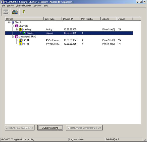 The BR/Console Audio Monitoring and Calibration window opens.
BR/Console Audio Monitoring and Calibration Window – Scope Test Tab 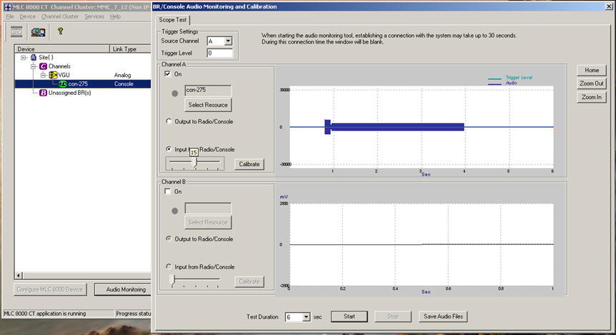
- If the scope test tab data fields do not appear as shown in the previous step, click Scope Test.
- To calibrate the input from the console to the MLC 8000 Analog Comparator (VGU), press PTT on your console and measure the power of the High Level Guard Tone (HLGT) signal with the Oscilloscope. The nominal level of HLGT should be -4 dBm with a variance of –22.5 to 15 dB. For values outside of this range, check your setup.
Oscilloscope 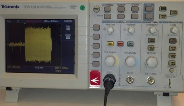
While the console is connected to port 1 of the MLC 8000 Analog Comparator (VGU), the power measurement is done using pins 3 and 4 of the VGU port side of the cable using the high impedance probe.
Probes to Cable Connection 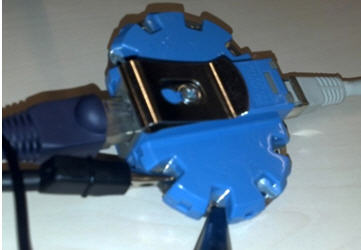
- Obtain the HLGT measurement:
- Connect probe channel 1 to RJ45 pins 3 and 4.
- Verify that you see the signal on the Oscilloscope. If not, swap pins 3 and 4.
- Set Channel 1 to AC coupling, SEC/DIV to 25 msec per division, and VOLTS/DIV according to the HLGT amplitude. Using the TRIG Menu button, set the trigger source to CH1 and Normal.
- Bring the level of the trigger to the upper half of HLGT.
- Use the Single Seq and Run/Stop buttons until the HLGT is cached.
- Obtain the Vpp of the HLGT signal (per the Volt division set above).
- Use the following formula for Power in the dBm computation:
P = 10*log10(1000 * ((Vpp’/2)*0.707)^2/600)
Where Vpp’ = Vpp * 2 because one probe is in use instead of two probes.
For example, Vpp’ = Vpp * 2 = 2.4 Volts. So, P=0.79 dBm.
- To set the slider value appropriately, use the calculated power from the previous step and the slider to HLGT signal power range table. See Slider to HLGT Signal Power Range.
- Press Calibrate.
A message appears asking for confirmation that the configuration of the analog comparator has been completed successfully.
- Click OK.
A message is displayed indicating that auto level control is activated.
- Click OK.
Calibration has been completed successfully.