Opening the Analog Display and Control Application with MLC 8000 Analog Comparator Selected
Prerequisites:
- The MLC 8000 Configuration Tool is operational. See procedure Opening the MLC 8000 Configuration Tool.
- The channel cluster containing the MLC 8000 Analog Comparator you want to monitor is opened and the associated channel cluster tree displayed on the main screen. See procedure Opening a Conventional Channel Cluster.
When and where to use:
Use this procedure to open the MLC 8000 Analog Display and Control Application for a particular MLC 8000 Analog Comparator. In mixed mode systems, monitor the digital comparator with a different monitoring tool (CSS or CTI).Procedure:
- Select the MLC 8000 Analog Comparator you want to monitor. You may be asked to log in for the MLC 8000 Analog Comparator you selected. If so, enter User Name and Password.
- Click MLC 8000 Analog Display and Control Application in the upper left-hand corner of the MLC 8000 Configuration Tool main screen.
The MLC 8000 Analog Display and Control Application window opens.
MLC 8000 Analog Display and Control Application 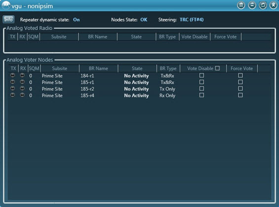
The top of the screen shows the dynamic repeat state of the Voter (on or off). The dynamic repeat state of the Voter is set at the console. Press the Info button for additional information about the MLC 8000 Analog Comparator (VGU) such as:
- Voice Repeater Operation Status: Enabled or Disabled
- Priority: Repeat over Console or Console over repeat
- Console Type: TRC or E&M
- Digital Channel Number associated with this channel (only if this is a mixed mode channel)
- Voting Method: Continuous voting, Vote and Hold, and Regional Voting
- Voter Type: Analog Only, Mixed Mode, or Analog IP Simulcast
- Transmitter Steering: Enabled or Disabled
NoteSteering details if steering type is Voted or TRC and the node/function tone by which steering was determined.
MLC 8000 Analog Comparator Information Window 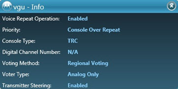
The left-hand column is the analog voter node LED display. The following are the color display variations along with an explanation on the meaning of each.
- Tx LED is red: The radio is transmitting.
- Rx LED is green: The radio is receiving.
- Gray: The radio is idle (neither transmitting or receiving).
Tx LED is red and Rx LED is green: The radio is transmitting and receiving.
The Subsite column displays the subsite name. The BR Name column displays the base radio name. The State column provides the state of the link to the base radio. The State column can display the following states:
- Active: The base radio is active and operational.
- No Activity: The base radio is operational but there is no current activity.
- Failed: The MLC 8000 Subsite Link Converter (AGU) has determined that the base radio has failed. If you move your cursor over “Failed”, a tool tip displays indicating the failure reason.
- Disabled: The base radio is disabled and thus incoming streams from this base radio are not used for voting by the MLC 8000 Analog Comparator (VGU).
The SQM column displays the signal strength the base radio measures. If there is no signal being measured for the radio, the column displays N/A. When a particular base radio is force voted , the others base radios continue to be displayed with their real SQM values unless the voting method is vote and hold, in which case the oSQM values of the other base radio are displayed as 0. When a particular base radio is displayed with an SQM of zero, it means that either this base radio is not receiving the current RF transmission, or it is receiving the current RF transmission but it has a synchronization problem with the MLC 8000 Analog Comparator (VGU), meaning their clocks are not synchronized while the voting method is set to continuous voting.
The BR Type column displays the type of the base radio, which can be Rx, Tx, or Rx and Tx.
The Vote Disable column is used to disable the vote for the analog base radio. The box should be checked in this column for each base radio for which voting should be disabled. When this box is checked, incoming streams from the base radio are not used for voting by the MLC 8000 Analog Comparator.
NoteIf several base radios have been disabled for voting, they can be enabled all at once by checking the box to the right of the Disable Vote column title.The Force Vote column is used to specify whether the analog base radio should be the radio selected. Only one base radio can be selected as the force vote. When a particular radio is force voted, voting is not used and the force voted radio is the radio that is used.
The Voted Radio section contains information about the voted base radio. Note that there is not always an obvious correlation between the SQM values shown in the list of base radios and the voted base radio. This lack of an obvious correlation is because the voting algorithm considers many factors, not all of which are obvious. For example, if a particular base radio has been restarted, it takes a few seconds for this base radio to synchronize with the voter. Until this synchronization is achieved, the base radio is not voted regardless of its SQM value. If the base radio is restarted while a call is being processed, the MLC 8000 Analog Comparator (VGU) is not able to synchronize with the base radio until after the call ends. As a result, this base radio cannot become the voted radio for a longer period.
NoteIf you perform configuration changes to an MLC 8000 Analog Comparator (VGU) monitored by the Analog Display and Control application, such as changing the list of base radios associated with it, an operation of force vote or disable vote is reset. This situation occurs whether the operation was set on the PC used to configure the channel cluster or a satellite PC. Reissue the disable vote or force vote operation using the Analog Display and Control application using the Vote Disable or Force Vote check box.