Circuit-Based Analog-Only Simulcast Voting Subsystem Equipment Cabling
This section provides a high-level subsystem diagram and equipment cabling tables from the MLC 8000 device to other system devices. A port description table lists the system devices and refers to the device documentation for more information.
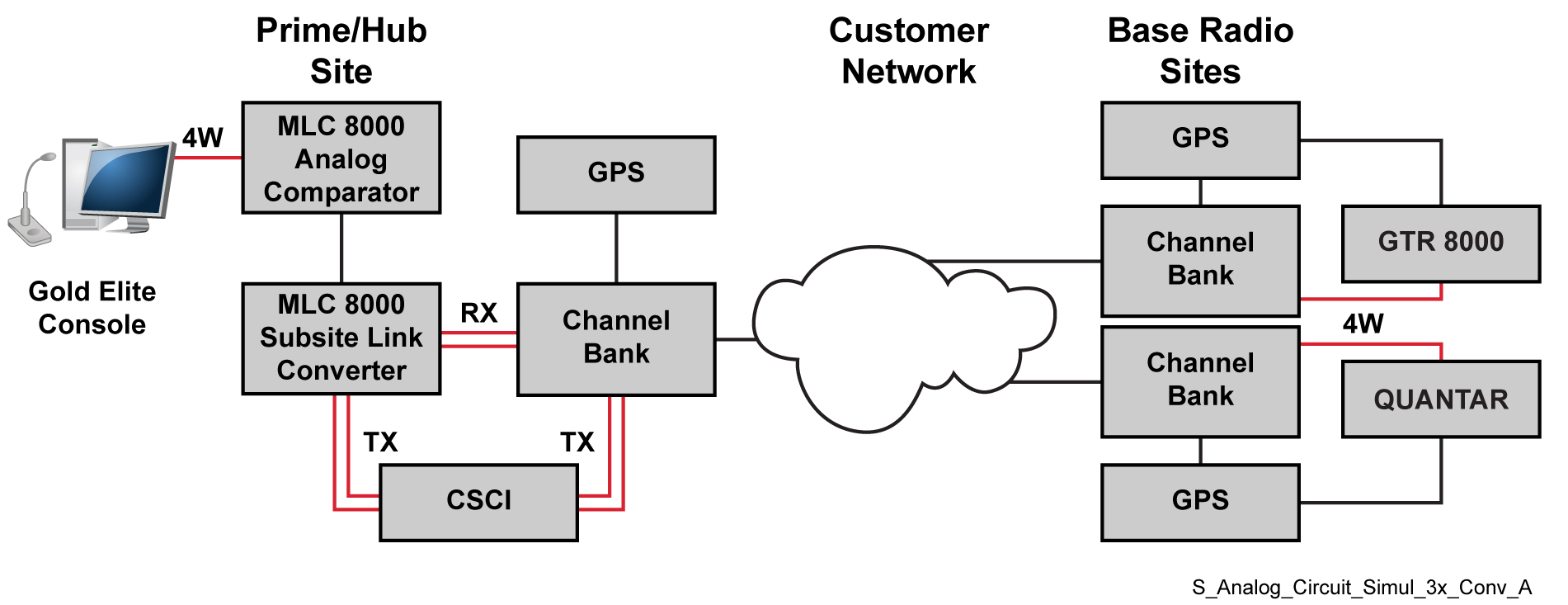
ImportantHigh-level diagrams are provided as examples only and are not to be used for system planning purposes. “GPS” in the diagram refers to a Simulcast Site Reference device.
NoteThis table provides part numbers for cables that are orderable from Motorola Solutions. Create the remaining cables using the provided pinout tables. See
MLC 8000 Radio Ports Cabling.
| From MLC 8000 Analog Comparator (Prime Site) | To Destination device: | |||
|---|---|---|---|---|
| Port | Connector Type | Device | Connector Type | Description |
| External LAN PoE | RJ45 | Ethernet Switch (not shown, connects to the MLC 8000 Subsite Link Converter) | RJ45 | RJ45-to-RJ45 one-to-one cable |
| R1 4W-E&M | RJ45 | MC2500 | DB25 | 4-Wire MLC 8000 to MC2500 Analog Console Cable |
| VIP | RJ45 | SDM3000 RTU | I/O Wiring Punch Block | MLC 8000 to SDM3000 RTU Cable |
| From MLC 8000 Subsite Link Converter (Prime Site) | To Destination device: | |||
| Port | Connector Type | Device | Connector Type | Description |
| External LAN PoE | RJ45 | Ethernet Switch (not shown, connects to the MLC 8000 Analog Comparator) | RJ45 | RJ45-to-RJ45 one-to-one cable |
| R1-4 4W-E&M | RJ45 | CSCI | Punch Block | CENTRACOM to MLC 8000 through CTI |
| VIP | RJ45 | SDM3000 RTU | I/O Wiring Punch Block | MLC 8000 to SDM3000 RTU Cable |
| R1-4 COMM | RJ45 | Channel Bank | RJ45 | 4W MLC 8000 to Channel Bank DSM-II Card Cable (Circuit-Based Simulcast) |
Port Descriptions for Circuit-Based Conventional Analog-Only Simulcast Voting Subsystem
| Device | Manual |
|---|---|
| MLC 8000 | See “MLC 8000 Ports” in the MLC 8000 Comparator Feature Guide. |
| Ethernet Switch | See the manufacturer’s manual. |
| MC2500 analog console | See the MC2500™ Multi-channel Deskset L3217 Operator and Installation Manual (6880309L14). |
| SDM3000 RTU | See the Installation chapter “Connecting I/Os with Punch Blocks” sub-section and Appendix C “Pin Assignments” and “Punch Block Terminal Block Contacts” in the SDM3000 Site Device Manager User Guide. |
| CSCI | See “CSCI-to-Punchblock Cabling” in the GPS Simulcast Installation manual (6881098E65). Refers to a legacy comparator, but this is applicable to the MLC 8000. |
| Channel Bank | See “DSM-II Pinouts” in the GPS Simulcast Installation manual (6881098E65). |