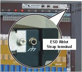
ESD Protection
The ESD wrist strap terminal is located on the upper front side of the shelf, and must be used prior to working on any part or electronic component.
This section contains steps for commissioning the HiperMAX GPS shelf, ATCA Shelf, SDR blades and Switch blades.
ESD ProtectionThe ESD wrist strap terminal is located on the upper front side of the shelf, and must be used prior to working on any part or electronic component.
|
|
There are two pluggable PEMs (Power Entry Modules). Each PEM provides power terminals for four 25A power feeds. There are two 30A fuses for each power feed at -48V and VRTN. The minimum input voltage is -40.5VDC and the maximum is -72VDC.
Before inserting any blades, plug in the shelf manager, turn on the -48V and measure the voltage on the PEMs. Note when the chassis are powered the fans go to full speed and then slow down once the Shelf Manager control loop kicks in. If the -48V is connected the wrong way the chassis will not power up.
See GPS Receiver Commissioning
If only one shelf manager is installed is should be installed in the upper slot.
See Shelf Manager Configuration
Apply Power to SCRTs
Set op a test ST and pass data over the system (ie FTP files)
There are 3 telco alarm LEDs (minor, major, critical), The teleco alarm push button that activates the alarm cutoff state (ACO). When ACO is activated, the active alarm LEDs blinks and all the alarm relays are deactivated. This button does not clear alarms.