Configuring an MLC 8000 Analog Comparator for an IP Simulcast System
Prerequisites:
- The MLC 8000 Configuration Tool is operational. See procedure Opening the MLC 8000 Configuration Tool.
- This MLC 8000 Analog Comparator is being configured for an IP simulcast system.
- The MLC 8000 Analog Comparator you want to modify has already been added to the conventional channel cluster. See procedure Adding an MLC 8000 Analog or Mixed Mode Comparator to a Conventional Channel Cluster.
When and where to use:
Use this procedure to modify the configuration of an MLC 8000 Analog Comparator (VGU) that has been added to the conventional channel cluster.Procedure:
- If an incorrect channel cluster is open and viewable from the main screen of the MLC 8000 Configuration Tool, close it by clicking .
- Click . Select the channel cluster which contains the MLC 8000 Analog Comparator you want to configure from the System folder and click OK.
The channel cluster opens and is displayed on the main screen of the MLC 8000 Configuration Tool.
- On the view of the channel cluster tree on the MLC 8000 Configuration Tool main screen, find the MLC 8000 Analog Comparator you want to configure. Right-click on the MLC 8000 Analog Comparator and select Configure Device.
The Modify Device Configuration window appears. From this window, you are able modify various parameters.
Modify Device Configuration Window – General Properties Tab for a VGU in an IP Simulcast System 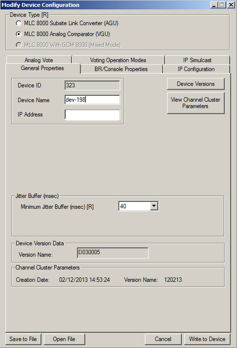
- Verify that radio button MLC 8000 Analog Comparator (VGU) is selected as the device type in the Device Type field at the top of the window . If not already selected, click MLC 8000 Analog Comparator (VGU).
ImportantIf MLC 8000 Analog Comparator (VGU) was not already selected, a confirmation dialog box appears. Click Yes.
- If the General Properties tab is not active, click General Properties to display the general properties-related fields.
The general properties-related fields appear.
- Specify or modify the device name, up to 19 alphanumeric characters, in the Device Name field. The device name is a user-friendly name for the MLC 8000 Analog Comparator device. This name continues to be displayed in this application until it is changed again, and it is useful for device identification.
ImportantIf you modify the device name, the MLC 8000 Analog Comparator is restarted to implement the change. The IP address is shown here for informational purposes only. It cannot be changed on the General Properties tab. To modify the IP address, the IP address field under the IP Configuration tab must be used.
- In the Minimum Jitter Buffer (msec) field, select the minimum jitter buffer length (in msec, multiples of 10) . The default value for this field is 20 msec. The valid range for VGU Minimum jitter buffer is 10 to 50 msec. Note that the MLC 8000 Analog Comparator jitter buffer is for the inbound IP traffic from the MLC 8000 Subsite Link Converter. The link jitter causes a variance in the link delay; the jitter buffer compensates this variance.
ImportantIf you modify the jitter buffer length, the MLC 8000 Analog Comparator is restarted to implement the change.
- Select the BR/Console Properties tab.
The base radio properties fields are displayed. These fields are display-only fields.NotePort ID, Console Name, and Console Keying Method are identifiers the system provides for the console that is attached to the MLC 8000 Analog Comparator (VGU) through port 1 by a 4-wire cable. Note that even when there is not a console attached to the MLC 8000 Analog Comparator, the system provides these identifiers.
Modify Device Configuration Window – BR/Console Properties Tab for a VGU in an IP Simulcast System 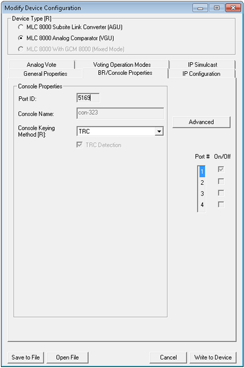
- Specifies the type of the Console Keying Method connected to the selected port as TRC or E&M. In case Console Keying Method is E&M, set the TRC detection field to enable it or leave it unchecked. If checked, the Advanced button will be able to be selected and TRC handling will be operational (TRC detection is turned on and the notch filter is turned on). If unchecked the Advanced button will be grayed out and there will not be any TRC handling (TRC detection is turned off and the notch filter is turned off). In case Console Keying Method is TRC, the TRC detection field can only be checked.
- Click Advanced to open the MLC 8000 Analog Comparator Console Advanced Configuration window.
The Console Advanced Configuration window opens.
Modify Device Configuration Window – BR Advanced Main Tab for a VGU in an IP Simulcast System 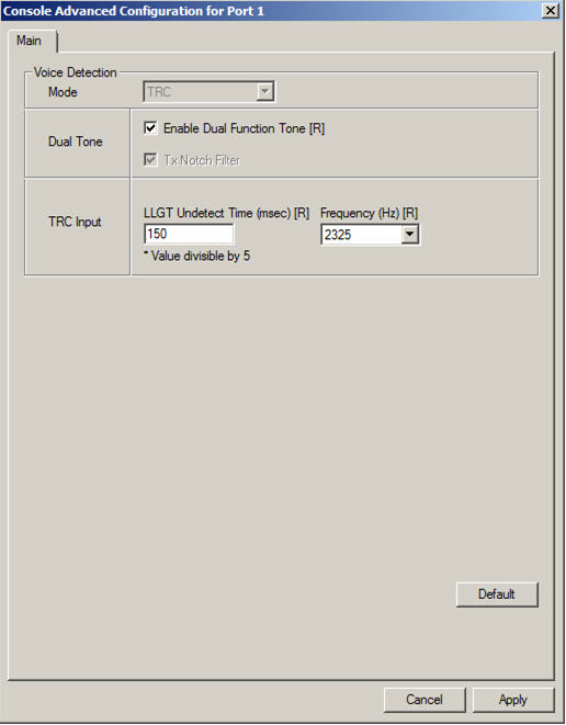
- In the Dual Tone field, select Enable Dual Function Tone if dual function tone should be enabled, meaning that TRC signaling from the console to the radio contains two function tones. If this field is not selected, dual function tone is disabled and signaling from the console to the base radio contains one function tone.
ImportantIf you modify the enable dual function tone setting, the MLC 8000 Analog Comparator is restarted to implement the change.
- In the TRC Input section, set LLGT Undetect Time (msec) to an integer from 60 to 2000 msec, in 5 msec steps. LLGT Undetect Time is the time from the moment the MLC 8000 Analog Comparator no longer detects LLGT to the moment that MLC 8000 Analog Comparator declares a call session end. The default value is 150 msec.
ImportantIf you modify the LLGT Undetect Time length, the MLC 8000 Analog Comparator is restarted to implement the change.
- In the TRC Input area, set the Frequency (Hz) by selecting the desired value from the drop-down list. The frequency should be set as per the HLGT frequency the console generates. Allowable values are 2100, 2175, and 2325 Hz. The default value for this field is 2175 Hz.
ImportantIf you modify the TRC input frequency, the MLC 8000 Analog Comparator is restarted to implement the change.
- Click Apply.
The Console Advanced Configuration window closes.
- Select the Analog Vote tab.
The Voter-ID is displayed along with the other voter property fields.
Modify Device Configuration Window – Analog Vote Tab for a VGU in an IP Simulcast System 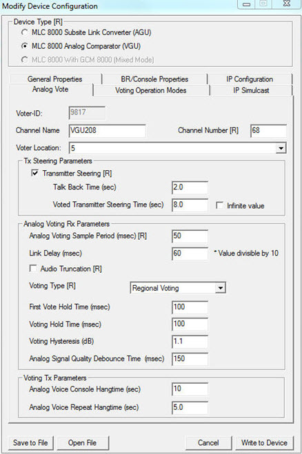
- Enter a channel name of up to 31 alphanumeric characters in the Channel Name field.
ImportantIf you modify the channel name, the MLC 8000 Analog Comparator is restarted to implement the change.
- Enter a number from 1 to 200 for the channel number assigned to the voter in the Channel Number field.
ImportantIf you modify the channel number, the MLC 8000 Analog Comparator is restarted to implement the change.
- Set the steering fields:
- Transmitter Steering: Enables the Transmitter Steering option, When selected, other related fields are enabled and the Voting Type field is automatically set to Regional Voting by default.
-
Talk Back Time (sec): Allows radio users and the dispatchers to converse while maintaining the call activity within a region (an area with multiple BRs/subsites used with Regional Voting) or a sub-site (a single BR used with Vote and Hold).
For Regional Voting, started when the radios from the active region have de-keyed and the dispatcher has de-keyed. Holds the list of receivers from the first voted BR so the radio users and dispatchers can converse. If expired, audio from any BR can be voted. Default value is 2.0.
For the Vote and Hold, started when the radio from the voted BR has de-keyed and the dispatcher has de-keyed. Holds the first voted BR, so the radio users and dispatchers can converse. If expired, audio from any BR can be voted. Default value is 0.0.
For Continuous Voting, the Talk Back Time is not valid as the BR with the strongest RF signal is the voted subsite. The Talk Back Time is only valid when Transmitter Steering is enabled. It is expected for the Talk Back Time to be shorter than the Transmitter Steering time. Values range between 0-100 in increments of 0.1 sec.
NoteIt is recommended that the Talk Back Time is set longer than both the Analog Voice Repeat Hangtime and the Analog Voice Console Hangtime or a call from another region is transmitted when the Talk Back Time expires and the hangtime is active. - Voted Transmitter Steering Time (sec): Allows the dispatchers to respond back to the transmitters list of the last voted BR. Timer is started when all radios and dispatcher have de-keyed. Holds the last voted BR for the dispatcher to respond back to, even after the call is over. If expired, the voted BR is no longer valid. All voting methods use this timer. The Voted Transmitter Steering Time is only valid when Transmitter Steering is enabled. It is expected for the Talk Back Time to be shorter than the Transmitter Steering time. Values range between 0-100000 in increments of 0.1 sec. Default value is 8.0.
- Infinite Value: If selected, Voted Transmitter Steering Time never expires. Default is not selected.
- Select Prime Site or an appropriate subsite from the drop-down list in the Voter Location field. If this subsite is not a prime site and the subsite required is not shown in the drop-down list of subsites from which to choose, select Add Subsite. Once this subsite is selected, the SubSite List window appears, allowing selection of a Subsite ID. Select the Subsite ID by clicking the row, and next the Modify Name for Subsite button should be clicked and a name entered for the Subsite. Click OK and then Apply. The subsite added can now be selected from the drop-down menu in the Voter Location field.
- Using the Analog Voting Sample Period (msec) field, set the SQM sampling window length to a value from 5 to 10000 msec. The default value is 50 msec.
ImportantIf you modify the analog voting sample period, the MLC 8000 Analog Comparator is restarted to implement the change.
- Set audio truncation by either selecting the Audio Truncation field to enable it. If selected, the default value, inbound audio samples used for calculating the SQM are discarded and the audio is played with truncation. If unselected, the inbound audio samples used to calculate the SQM are played, causing the user to hear the voice with delay in respect to the voice coming from the radio.
ImportantIf you modify audio truncation, the MLC 8000 Analog Comparator is restarted to implement the change.
- Select the Voting Type:
- Vote and Hold: A single vote is performed at the beginning of the call. The analog first vote hold time field is ignored when the vote and hold operation is selected.
- Continuous Voting: The signal is periodically voted throughout the analog call. Also for Continuous Voting, the analog first Vote Hold parameter is set to the default value.
- Regional Voting: Once the analog comparator votes a subsite, the analog comparator allows another subsite to be voted if the subsite is in the region of the first voted subsite. Regional Voting is only valid when Transmitter Steering is enabled. When Transmitter Steering is disabled, the Voting Type defaults to Continuous Voting. When Transmitter Steering is enabled, the Voting Type is defaulted to Regional Voting.
- Set link delay to a value from 60 to 300 msec using the Link Delay (msec) field. From the first SQM value received at the voter, the voter starts the link delay timer and collects all SQM values in between. The default value is 80 msec.
- Specify first vote hold time in the First Vote Hold Time (msec) field.
- Specify the voting hold time in the Voting Hold Time (msec) field.
- Specify voting hysteresis in the Voting Hysteresis (dB) field.
- Enter the analog signal quality debounce time in the Analog Signal Quality Debounce Time (msec) field.
- Specify analog voice console hangtime in the Analog Voice Console Hangtime (sec) field.
- Specify analog voice repeat hangtime in the Analog Voice Repeat Hangtime (sec) field.
- Select the Voting Operation Modes tab.
The fields associated with voting operation modes appear.
- TRC Regional Time (sec): While in TRC Transmitter Steering mode (from the Console Frequency Select), started when the dispatchers and radios have de-keyed, and canceled when audio is received from a dispatcher or a radio within the selected region. If expired, the TRC Transmitter Steering mode is de-activated and Voted Transmitter Steering is applied. The TRC Regional Time is only valid when Transmitter Steering is enabled and the Voting Type is Regional Voting. Values range between 0-100000 in increments of 1 sec. Default is Infinite.
- Infinite Value: If selected, TRC Regional Timer never expires. The TRC Regional Timer default value is enabled.
Modify Device Configuration Window – Voting Operation Modes Tab for a VGU in an IP Simulcast System 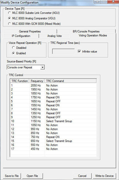
- Click Disabled or Enabled in the Voice Repeat Operation section to select whether the voice repeat operation is disabled or enabled.
NoteChoose Voice Repeat Operation Enabled if the audio should be repeated among subscribers and not just from the subscriber to the analog console. If you modify the voice repeat operation setting, the MLC 8000 Analog Comparator is restarted to implement the change.
- Set the signal priority based on the device that sourced the signal arriving at the VGU port using the drop-down list in the Source-Based Priority field. Select Console over Repeat if an outbound signal (arriving from the console) should have a higher priority than an inbound signal (arriving from the radio). Select Repeat over Console if an inbound signal (arriving from the BR) should have a higher priority than an outbound signal.
ImportantIf you modify the source-based priority, the MLC 8000 Analog Comparator is restarted to implement the change.
- If the IP address or the speed and duplex setting of the MLC 8000 Analog Comparator should be changed, select the IP Configuration tab. If not, continue with step 25.
The IP Configuration fields appear.
Modify Device Configuration Window – IP Configuration Tab for a VGU in an IP Simulcast System 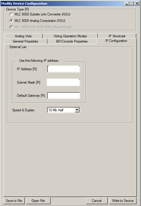
- Enter the IP address in the IP Address field.
NoteFor MLC 8000 devices implemented in ASTRO ® 25 systems, contact your system administrator for the appropriate IP address.
- Enter the subnet mask IP address in the Subnet Mask field.
NoteFor MLC 8000 devices implemented in ASTRO ® 25 systems, contact your system administrator for the appropriate IP address.
- Enter the default gateway IP address in the Default Gateway field.
NoteFor MLC 8000 devices implemented in ASTRO ® 25 systems, contact your system administrator for the appropriate IP address.
- Set the speed and duplex to 10 Mb Full, 10 Mb Half, 100 Mb Full, 100 Mb Half, or Auto in the Speed & Duplex field.
- Select the IP Simulcast tab. Note that this tab appears only in IP simulcast configurations.
The IP simulcast fields appear.ImportantIf you modify any of the IP Simulcast parameters, the MLC 8000 Analog Comparator is restarted to implement the parameter change.
Modify Device Configuration Window – IP Simulcast Tab for a VGU in an IP Simulcast System 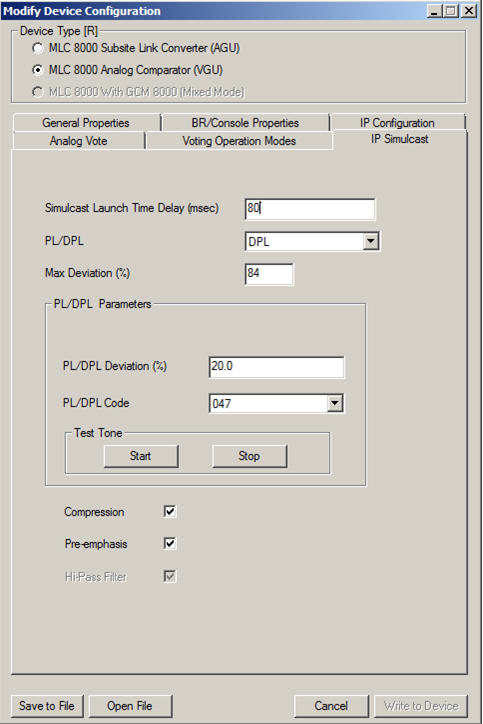
- Set the simulcast launch time delay value to a value from <0> to <990> msec (milliseconds) in the Simulcast Launch Time Delay (msec) field. The default value is 70 msec.
NoteIf you set Simulcast Launch Time Delay to a value lower than the IP network capability, audio degradation results. See procedure Determining the Simulcast Launch Time Delay in Analog IP Simulcast Systems for details on how this field should be calculated.
- Set the PL/DPL field to Private Line (PL), Digital Private Line (DPL), or Disabled to specify whether PL, DPL, or neither should be inserted into the voice stream.
ImportantIt is important that PL/DPL is set the same as it is for the base radios and the subscriber units.If the PL/DPL field was set to either PL or DPL, the PL/DPL Deviation and PL/DPL Code fields are open for editing.ImportantWhile these fields can be set at this time, it is recommended that they be set by following the calibration procedure for conventional IP simulcast. See procedure Calibrating Conventional Analog IP Simulcast.WarningThe fields related to PL/DPL, PL/DPL Deviation and PL/DPL Code, should not be touched after the analog IP simulcast system is calibrated per the customer PL/DPL code. If the PL/DPL code changes, the coarse level PL/DPL calibration must be re-executed for 20% system deviation.
- Enter 0 to 100in the Max Deviation (%) field to specify a percentage. The default value is 92%. The Max Deviation field defines transmit deviation as a percentage of the maximum station deviation, for the current channel.
- Select Compression to specify that compression and expansion should be executed on the voice signal.
ImportantCompression should be set the same as it is for the base radios and subscriber units.
- Select Pre-emphasis to cause the pre-emphasis of analog audio by passing through a filter with positive six db/octave slope before transmission. The signal is then de-emphasized on the receiving node.
ImportantPre-emphasis should be set the same as it is for the base radios and subscriber units.
- Select Hi-Pass Filter if you want to use a Hi-Pass filter to filter out high frequency tones.
Important When PL or DPL is enabled, the Hi Pass filter must be enabled and the Hi-Pass Filter field is grayed out and shows that it is automatically set to enabled. When PL/DPL is not set to PL or DPL, the Hi-Pass Filter field is available for editing. The default is enabled, because in most cases you want to clean up low frequencies should they exist. If for any reason you want to have the low frequencies in the MLC 8000 Analog Comparator (VGU) output toward the AGU, set Hi-Pass Filter to disabled by leaving the field unselected.
- Click Write to Device.
A dialog box appears asking for confirmation of the pending configuration change to the MLC 8000 Analog Comparator.
- Click OK.
The system saves the configuration changes. The Power LED changes to red. Wait for the Power LED to change to green before disconnecting or connecting any MLC 8000 cables.