ASTRO 25 Circuit-Based Analog-Only Simulcast Voting Subsystem Equipment Cabling
This section provides a high-level subsystem diagram and equipment cabling tables from the MLC 8000 device to other system devices. A port description table lists the system devices and refers to the device documentation for more information.
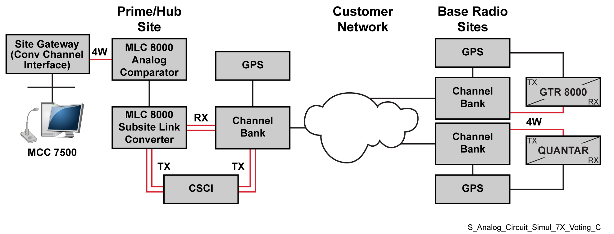
ImportantHigh-level diagrams are provided as examples only and are not to be used for system planning purposes. “GPS” in the diagram refers to a Simulcast Site Reference device. The GPS should be connected to the MLC 8000 Subsite Link Converter only if it is connected to an Rx/Tx or Tx only BR.
NoteThis table provides part numbers for cables that are orderable from Motorola. Create the remaining cables using the provided pinout tables. See
MLC 8000 Radio Ports Cabling.
| From MLC 8000 Analog Comparator (Prime Site) | To Destination device: | |||
|---|---|---|---|---|
| Port | Connector Type | Device | Connector Type | Description |
| External LAN PoE | RJ45 | LAN Switch | RJ45 | RJ45-to-RJ45 one-to-one cable |
| VIP | RJ45 | SDM3000 RTU | I/O Wiring Punch Block | MLC 8000 to SDM3000 RTU Cable |
| R1 4W-E&M | RJ45 | Site Gateway (Conventional Channel Interface), 4W E&M (8D…8A) | RJ45 | 4W MLC 8000 (Analog Comparator) to Site Gateway (Conventional Channel Interface) Cable |
| From MLC 8000 Subsite Link Converter (Prime Site) | To Destination device: | |||
| Port | Connector Type | Device | Connector Type | Description |
| External LAN PoE | RJ45 | LAN Switch | RJ45 | RJ45-to-RJ45 one-to-one cable |
| R1-4 4W-E&M | RJ45 | CSCI | Punch Block | CENTRACOM to MLC 8000 through CTI |
| R1-4 COMM | RJ45 | Channel Bank | SRU card | V.24 MLC 8000 to Channel Bank SRU Card Cable |
| VIP | RJ45 | SDM3000 RTU | I/O Wiring Punch Block | MLC 8000 to SDM3000 RTU Cable |
Port Descriptions for ASTRO 25 Circuit-Based Analog-Only Simulcast Voting Subsystem
| Device | Manual |
|---|---|
| MLC 8000 | See “MLC 8000 Ports” in the MLC 8000 Comparator Feature Guide. |
| LAN switch | See “HP Switches – Determining Port Connections in ASTRO 25 Systems” in the Ethernet LAN Switches Feature Guide. |
| SDM3000 RTU | See the Installation chapter “Connecting I/Os with Punch Blocks” sub-section and Appendix C “Pin Assignments” and “Punch Block Terminal Block Contacts” in the SDM3000 Site Device Manager User Guide. |
| Site Gateway (Conventional Channel Interface) | See “Making a Physical 4-W Connection on MLC 8000 Analog Comparator to CCGW” in the GGM 8000 System Gateway Feature Guide. |
| CSCI | See “CSCI-to-Punchblock Cabling” in the GPS Simulcast Installation manual (6881098E65). Refers to a legacy comparator, but this is applicable to the MLC 8000. |
| Channel Bank | See the GPS Simulcast Installation manual (6881098E65). |